
Description
-
Model List:
- L213 Tier 4B Final 200 Series Skid Steer Loader
- L216 Tier 4B Final 200 Series Skid Steer Loader
- L218 Tier 4B Final 200 Series Skid Steer Loader
- L220 Tier 4B Final 200 Series Skid Steer Loader
- L221 Tier 4B Final 200 Series Skid Steer Loader
- L228 Tier 4B Final 200 Series Skid Steer Loader
- C227 Tier 4B Final 200 Series Compact Track Loader
- C232 Tier 4B Final 200 Series Compact Track Loader
- C237 Tier 4B Final 200 Series Compact Track Loader
- 1. GENERAL INFORMATION
- 1.1. Note to the owner
- 1.2. ElectroMagnetic Compatibility (EMC)
- 1.3. Product identification
- 1.4. Operators manual storage on the machine
- 1.5. Machine orientation
- 1.6. Machine components
- 1.7. Emissions overview (L221, L228, C227, C232, and C237)
- 1.8. Emissions overview (L213, L216, L218, and L220)
- 2. SAFETY INFORMATION
- 2.1. Safety rules and signal word definitions
- 2.2. Safety rules
- 2.3. Utility safety
- 2.4. Proper entry and exit
- 2.5. Starting and stopping precautions
- 2.6. Seat belt precautions
- 2.7. Specific precautions to this machine
- 2.8. Fire extinguisher
- 2.9. Safety rules California Proposition 65 Warning
- 2.10. Roll Over Protective Structure (ROPS)
- 2.11. Welding on the machine
- 2.12. Loader arm lock and cab tilt procedure radial lift machines
- 2.13. Loader arm lock and cab tilt procedure vertical lift machines
- 2.14. No engine power loader arm up and down control
- 2.15. Emergency exit
- 2.16. Ecology and the environment
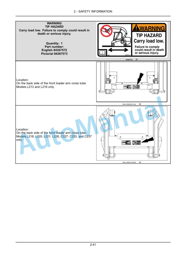
- 2.17. Safety signs
- 3. CONTROLS AND INSTRUMENTS
- 3.1. ACCESS TO OPERATORS PLATFORM
- 3.1.1. Door latches, cab
- 3.1.2. Window glass, cab
- 3.1.3. Windshield wiper and washer controls
- 3.1.4. Cab air louvers
- 3.2. OPERATORS SEAT
- 3.2.1. Standard seat
- 3.2.2. Mechanical suspension seat
- 3.2.3. Air seat
- 3.2.4. Seat belt operation
- 3.2.5. Shoulder belt
- 3.2.6. Restraint bar (if equipped)
- 3.3. MECHANICAL HYDRAULIC CONTROLS
- 3.3.1. Steering and travel
- 3.3.2. Lift arm and bucket controls
- 3.3.3. Moving the machine
- 3.3.4. Turning the machine
- 3.3.5. Hand controls
- 3.3.6. Foot controls
- 3.4. ELECTROHYDRAULIC CONTROLS
- 3.4.1. Control pattern overview
- 3.4.2. H control pattern steering and travel
- 3.4.3. H control pattern lift arm and bucket controls
- 3.4.4. ISO control pattern steering and travel
- 3.4.5. ISO control pattern lift arm and bucket controls
- 3.4.6. Standard H control pattern
- 3.4.7. Standard ISO control pattern
- 3.4.8. Electrohydraulic control handle adjustment
- 3.4.9. Hand controls
- 3.4.10. Moving the machine
- 3.4.11. Turning the machine
- 3.4.12. Lift arm raise/lower control
- 3.4.13. Bucket curl/dump control
- 3.4.14. Moving the machine
- 3.4.15. Turning the machine
- 3.4.16. Lift arm and bucket controls
- 3.5. CONTROL LEVERS
- 3.5.1. Switch configurations
- 3.5.2. Twospeed function
- 3.6. AUXILIARY HYDRAULICS
- 3.6.1. Standard auxiliary hydraulics
- 3.6.2. High flow auxiliary hydraulics
- 3.6.3. Enhanced High Flow (EHF) auxiliary hydraulics
- 3.7. INSTRUMENT CLUSTER
- 3.7.1. Electronic Instrument Cluster (EIC)
- 3.7.2. Advanced Instrument Cluster (AIC)
- 3.7.3. Instrument cluster
- 3.7.4. Instrument cluster SETUP menu
- 3.7.5. Instrument cluster display setting
- 3.7.6. ElectroHydraulic (EH) controllability selection
- 3.7.7. Temperature display selection
- 3.7.8. View or reset Job Timer (JTIME)
- 3.7.9. Regeneration inhibit
- 3.7.10. Oil life reset
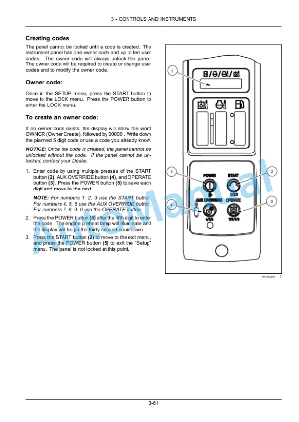
- 3.7.11. Antitheft protection
- 3.7.12. Instrument cluster timeout feature
- 3.7.13. Lefthand column switch identification
- 3.7.14. ISO or H pattern control switch
- 3.7.15. Machine lights
- 3.7.16. Radio (if equipped)
- 4. OPERATING INSTRUCTIONS
- 4.1. COMMISSIONING THE UNIT
- 4.1.1. Operating Instructions
- 4.2. STARTING THE UNIT
- 4.2.1. Engine operation
- 4.2.2. Operating in extreme temperatures
- 4.2.3. Throttle control
- 4.2.4. Booster battery procedure
- 4.3. STOPPING THE UNIT
- 4.3.1. Parking the machine and stopping the engine
- 4.4. MOVING THE UNIT
- 4.4.1. Machine operation
- 5. TRANSPORT OPERATIONS
- 5.1. SHIPPING TRANSPORT
- 5.1.1. Transporting the machine
- 5.2. RECOVERY TRANSPORT
- 5.2.1. Moving a disabled machine
- 6. WORKING OPERATIONS
- 6.1. GENERAL INFORMATION
- 6.1.1. Mechanical attachment mounting systems
- 6.1.2. Hydraulic attachment mounting systems
- 6.1.3. Field operation
- 7. MAINTENANCE
- 7.1. GENERAL INFORMATION
- 7.1.1. General safety before you service
- 7.1.2. Lubrication analysis program
- 7.1.3. Plastic and resin parts
- 7.1.4. Machine cleaning
- 7.1.5. Cab door removal and installation
- 7.1.6. Battery safety check and cleaning
- 7.1.7. Fire extinguisher
- 7.1.8. Engine hourmeter
- 7.1.9. Fluids and lubricants
- 7.1.10. Engine oil viscosity
- 7.1.11. Hydraulic oil viscosity
- 7.1.12. Organic Acid Technology (OAT) coolant
- 7.1.13. General specification Diesel fuel
- 7.1.14. General specification Biodiesel fuels
- 7.1.15. Lubrication and maintenance access
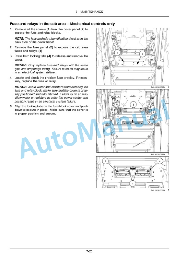
- 7.1.16. Fuses and relays
- 7.2. MAINTENANCE CHART
- 7.2.1. Maintenance chart
- 7.3. INITIAL 10 HOURS
- 7.3.1. Track tension check and adjustment
- 7.3.2. Tire pressure and wheel hardware torque
- 7.3.3. Alternator and air conditioning compressor (if equipped) belt tension (models L213, L216, L218, and L220 only)
- 7.4. EVERY 10 HOURS OR DAILY
- 7.4.1. Clean tracks and components
- 7.4.2. Engine and hydraulic coolers
- 7.4.3. Engine coolant level
- 7.4.4. Engine oil level
- 7.4.5. Loader arm pivot points, coupler pins, and cylinder pins
- 7.4.6. Hydraulic oil level
- 7.4.7. Loader arm and bucket hydraulic interlock
- 7.5. INITIAL 50 HOURS
- 7.5.1. Roll Over Protective Structure (ROPS) mechanism and hardware check
- 7.6. EVERY 50 HOURS
- 7.6.1. Track tension check and adjustment
- 7.6.2. Cab intake filter
- 7.6.3. Seat restraints Check
- 7.7. INITIAL 100 HOURS
- 7.7.1. Final drive oil (track models)
- 7.8. EVERY 250 HOURS
- 7.8.1. Inline fuel filter (models L213 and L216 only)
- 7.8.2. Fuelwater separator filter drain fluid
- 7.8.3. Drive chain tension check
- 7.8.4. Tire pressure and wheel hardware torque
- 7.9. EVERY 500 HOURS
- 7.9.1. Engine oil and filter
- 7.9.2. Fuelwater separator filter element
- 7.9.3. Fuel filter
- 7.9.4. Hydraulic oil filter
- 7.9.5. Final drive chain tank oil
- 7.9.6. Air cleaner elements
- 7.9.7. Final drive oil (track models)
- 7.9.8. Roll Over Protective Structure (ROPS) mechanism and hardware check
- 7.9.9. Cab door Grease
- 7.10. EVERY 1000 HOURS
- 7.10.1. Hydraulic fluid and filter
- 7.10.2. Final drive chain tank oil
- 7.10.3. Oil Mist Separator (OMS) filter (models L213, L216, L218, and L220 only)
- 7.11. EVERY 2000 HOURS
- 7.11.1. Blowby recirculation system (models L221, L228, C227, C232, and C237 only)
- 7.12. EVERY 4000 HOURS
- 7.12.1. Diesel Particulate Filters (DPF) Cleaning (models L213 and L216 only)
- 7.12.2. Engine cooling system Change fluid L213, L216, L218, and L220 only
- 7.12.3. Engine cooling system Change fluid L221, L228, C227, C232, and C237 only
- 7.13. AS REQUIRED
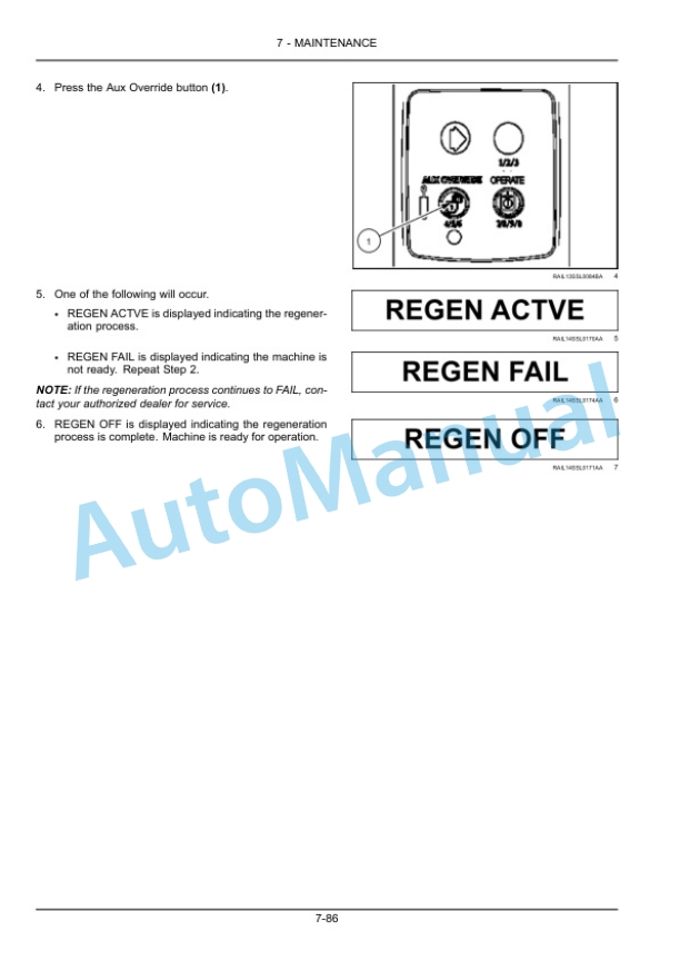
- 7.13.1. Autoregeneration
- 7.13.2. Manual regeneration
- 7.13.3. Hardware loose or damaged
- 7.13.4. Window removal and cleaning
- 7.14. STORAGE
- 7.14.1. Storing the machine
- 7.14.2. Preparing the machine after storage
- 8. TROUBLESHOOTING
- 8.1. FAULT CODE RESOLUTION
- 8.1.1. Display warnings
- 8.1.2. Fault code index
- 9. SPECIFICATIONS
- 9.1. Fluids and lubricants
- 9.2. General specification
- 9.3. Product identification attachments
- 9.4. Material weights
- 9.5. Units of measure and conversion
- 9.6. Torque charts Minimum tightening torques for normal assembly
- 10. ACCESSORIES
- 10.1. Telematics Overview with New Holland FleetForce


There are no reviews yet.