
Description
-
Model List:
- 3JH4(B)(C)(M)E
- 1. History of Revision
- 2. FOREWORD
- 3. CONTENTS
- 4. GENERAL
- 4.1. Exterior Views
- 4.2. Specifications
- 4.3. Engine Outline
- 4.4. Piping Diagrams
- 4.5. Exhaust Gas Emission Regulation
- 4.5.1. Engine identification (3JH4E)
- 4.5.2. Exhaust Gas Regulations
- 4.5.3. Guarantee Conditions for Emission Standard
- 5. Inspection and Adjustment
- 5.1. Periodic Maintenance Schedule
- 5.2. Periodic Inspection and Maintenance Procedure
- 5.2.1. Check before starting
- 5.2.2. inspection after initial 50 hours or one month operation
- 5.2.3. Inspection every 50 hours or monthly
- 5.2.4. Inspection every 250 hours or one year
- 5.2.5. Inspection every 1,000 hours or four years
- 5.3. Adjusting the no-load maximum or minimum speed
- 5.4. Sensor Inspection
- 5.4.1. Oil pressure switch
- 5.4.2. Thermo switch
- 5.5. Thermostat inspection
- 5.6. Adjusting Operation
- 5.6.1. Preliminary Precautions
- 5.6.2. Adjusting operation procedure
- 5.6.3. Check Points and Precautions During Running
- 5.7. Long storage
- 6. Troubleshooting
- 6.1. Preparation before troubleshooting
- 6.2. Quick Reference Chart for Troubleshooting
- 6.3. Troubleshooting (Concerning engine and fuel injection equipment)
- 6.4. Troubleshooting by measuring Compression Pressure
- 7. Disassembly and Reassembly
- 7.1. Disassembly and Reassembly Precautions
- 7.2. Disassembly and Reassembly Tools
- 7.2.1. General Handtools
- 7.2.2. Special Handtools
- 7.2.3. Measuring Instruments
- 7.2.4. Other material
- 7.2.5. Measuring Instruments
- 7.3. Disassembly and Reassembly
- 7.3.1. Disassembly
- 7.3.2. Reassembly
- 8. Inspection and Servicing of Basic Engine Parts
- 8.1. Cylinder Block
- 8.1.1. Inspection of parts
- 8.1.2. Cleaning of oil holes
- 8.1.3. Color check procedure
- 8.1.4. Replacement of cup plugs
- 8.1.5. Cylinder bore measurement
- 8.2. Cylinder Head
- 8.2.1. Inspecting the cylinder head
- 8.2.2. Valve seat correction procedure
- 8.2.3. Intake/exhaust valves, valve guides
- 8.2.4. Valve springs
- 8.2.5. Assembling the cylinder head
- 8.2.6. Measuring top clearance
- 8.2.7. Intake and exhaust rocker arms
- 8.2.8. Adjustment of valve clearance
- 8.3. Piston and Piston Pins
- 8.3.1. Piston
- 8.3.2. Piston pin
- 8.3.3. Piston rings
- 8.4. Connecting Rod
- 8.4.1. Inspecting the connection rod
- 8.4.2. Crank pin metal
- 8.4.3. Piston pin bushing
- 8.4.4. Assembling piston and connecting rod
- 8.5. Crankshaft and Main Bearing
- 8.5.1. Crankshaft
- 8.5.2. Main bearing
- 8.6. Camshaft and Tappets
- 8.6.1. Camshaft
- 8.6.2. Tappets
- 8.7. Timing Gear
- 8.7.1. Inspecting the gears
- 8.7.2. Gear timing marks
- 8.8. Flywheel and Housing
- 8.8.1. Position of top dead center and fuel injection timing
- 8.8.2. Damper disc and cooling fan
- 9. FUEL INJECTION EQUIPMENT
- 9.1. Fuel Injection Pump/Governor
- 9.1.1. Fuel system diagram
- 9.1.2. Fuel injection pump service data
- 9.1.3. Fuel injection pump structure
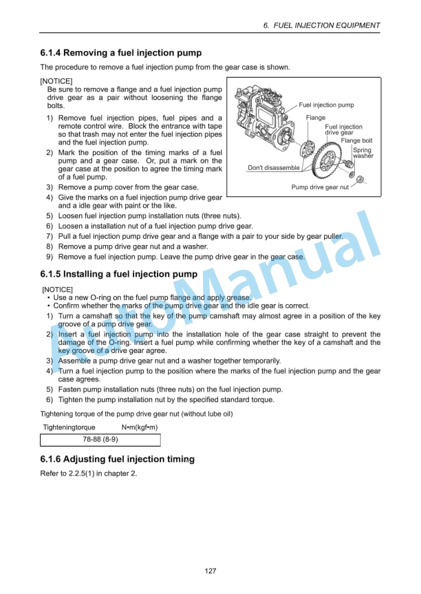
- 9.1.4. Removing a fuel injection pump
- 9.1.5. Installing a fuel injection pump
- 9.1.6. Adjusting fuel injection timing
- 9.1.7. Troubleshooting of fuel injection pump
- 9.1.8. Major faults and troubleshooting
- 9.1.9. Tools
- 9.2. Fuel Feed Pump
- 9.2.1. Construction of fuel feed pump
- 9.2.2. Fuel feed pump specifications
- 9.2.3. Disassembly and reassembly of fuel feed pump
- 9.2.4. Fuel feed pump inspection
- 9.3. Fuel Filter
- 9.3.1. Fuel filter specifications
- 9.3.2. Fuel filter inspection
- 9.4. Fuel Tank
- 10. INTAKE AND EXHAUST SYSTEM
- 10.1. Intake System
- 10.1.1. Breather system (A reductor to intake air system of blowby gas)
- 10.1.2. Diaphragm assy inspection
- 10.2. Exhaust System
- 10.2.1. Construction
- 10.2.2. ixing elbow inspection
- 11. LUBRICATION SYSTEM
- 11.1. Lubrication System
- 11.2. Lube Oil Pump
- 11.2.1. Lube oil pump construction
- 11.2.2. Specifications of lube oil pump
- 11.2.3. Lube oil pump disassembly and reassembly
- 11.2.4. Lube oil pump inspection
- 11.2.5. Oil pressure control valve construction
- 11.3. Lube Oil Filter
- 11.3.1. Lube oil filter construction
- 11.3.2. Lube oil filter replacement
- 11.4. Lube oil Cooler
- 11.4.1. Lube oil cooler construction
- 11.4.2. Inspecting the lube oil cooler
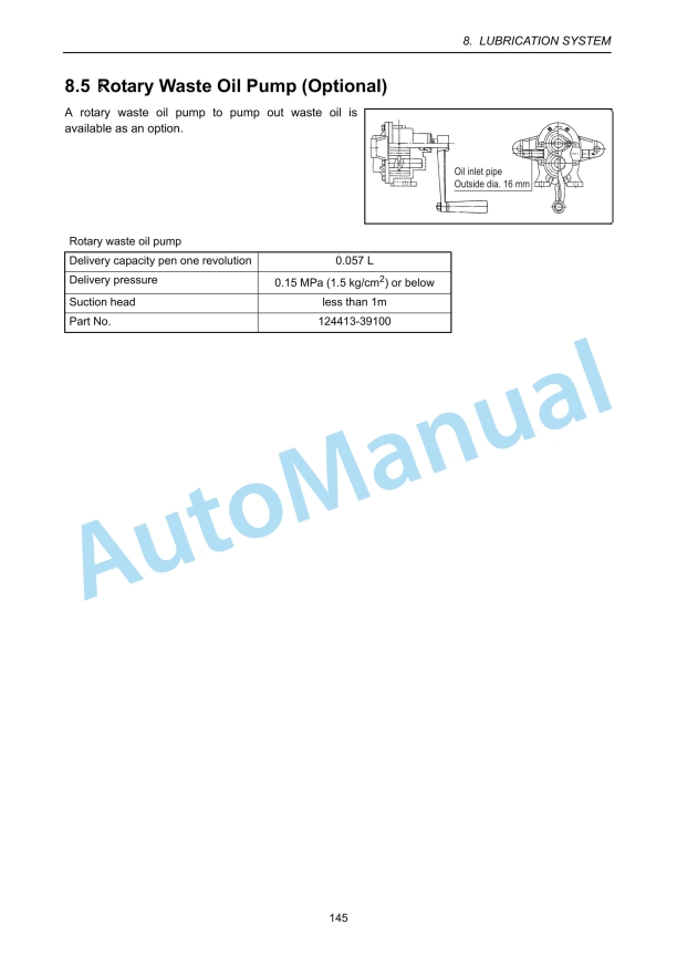
- 11.5. Rotary Waste Oil Pump (Optional)
- 12. Cooling Water System
- 12.1. Cooling Water System
- 12.2. Seawater Pump
- 12.2.1. Specifications of seawater pump
- 12.2.2. Seawater pump disassembly
- 12.2.3. Seawater pump Inspection
- 12.2.4. Seawater pump reassembly
- 12.3. Fresh Water Pump
- 12.3.1. Fresh water pump construction
- 12.3.2. Specifications of fresh water pump
- 12.3.3. Fresh water pump disassembly
- 12.3.4. Fresh water pump inspection
- 12.4. Heat Exchanger
- 12.4.1. Heat exchanger construction
- 12.4.2. Specifications of heat exchanger
- 12.4.3. Disassembly and reassembly of the heat exchanger
- 12.4.4. Heat exchanger inspection
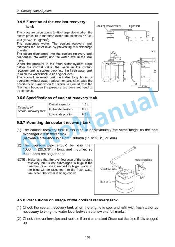
- 12.5. Pressure cap and coolant recovery tank
- 12.5.1. Pressure cap construction
- 12.5.2. Pressure cap pressure control
- 12.5.3. Pressure cap inspection
- 12.5.4. Replacing filler neck
- 12.5.5. Function of the coolant recovery tank
- 12.5.6. Specifications of coolant recovery tank
- 12.5.7. Mounting the coolant recovery tank
- 12.5.8. Precautions on usage of the coolant recovery tank
- 12.6. Thermostat
- 12.6.1. Functioning of thermostat
- 12.6.2. Thermostat construction
- 12.6.3. Characteristics of thermostat
- 12.6.4. Thermostat inspection
- 12.6.5. Testing the thermostat
- 12.7. Bilge Pump and Bilge Strainer (Optional)
- 12.7.1. Introduction
- 12.7.2. Description
- 12.7.3. Cautions
- 12.7.4. Assembly Procedure
- 12.7.5. Cautions for Assembling
- 12.7.6. Troubleshooting
- 13. Reduction and Reversing Gear
- 14. REMOTE CONTROL (OPTIONAL)
- 14.1. Remote Control system
- 14.1.1. Construction of remote control system
- 14.1.2. Remote control device components
- 14.2. Remote Control Installation
- 14.3. Remote Control Inspection
- 14.4. Remote Control Adjustment
- 15. Electrical System
- 15.1. Electrical System
- 15.1.1. Wiring diagram
- 15.2. Battery
- 15.3. Starting Motor
- 15.3.1. Specifications
- 15.3.2. Characteristics
- 15.3.3. Structure
- 15.3.4. Wiring diameter of a starting motor
- 15.4. Alternator Standard, 12V/60A
- 15.4.1. Specifications
- 15.4.2. Structure
- 15.4.3. Wiring diagram
- 15.4.4. Standard output characteristics
- 15.4.5. Inspection
- 15.5. Alternator 12V/80A (Optional)
- 15.5.1. Specifications
- 15.5.2. Structure
- 15.5.3. Wiring diagram
- 15.5.4. Standard output characteristics
- 15.6. Instrument Panel
- 15.6.1. B-type instrument panel (optional)
- 15.6.2. C-type instrument panel
- 15.7. Warning Devices
- 15.7.1. Oil pressure alarm
- 15.7.2. Sender unit for lube oil pressure gauge
- 15.7.3. Cooling water temperature alarm
- 15.7.4. Sender unit for the cooling water temperature gauge
- 15.8. Air Heater (Optional)
- 15.9. Electric Engine Stopping Device (Optional)
- 16. SERVICE STANDARDS
- 16.1. Engine Tuning
- 16.2. Engine Body
- 16.2.1. Cylinder head
- 16.2.2. Camshaft and gear train
- 16.2.3. Cylinder block
- 16.3. Lubricating Oil System (Trochoid Pump)
- 17. TIGHTENING TORQUE FOR BOLTS AND NUTS
- 17.1. Main Bolt and Nut
- 17.2. Standard Bolts and Nuts (without lube oil)
- 18. Back cover
(C)(M)E%20Service%20Manual&url=https://pdfrepairmanual.com/docs/yanmar-3jh4bcme-service-manual/&media=https://pdfrepairmanual.com/wp-content/uploads/2026/01/yanmar-3jh4bcme-service-manual-1.jpg)


,%202GM20(F)(C),%203GM30(F)(C),%203HM35(F)(C)%20Engine%20Service%20Manual&url=https://pdfrepairmanual.com/docs/yanmar-1gm10c-2gm20fc-3gm30fc-3hm35fc-engine-service-manual/&media=https://pdfrepairmanual.com/wp-content/uploads/2026/01/yanmar-1gm10c-2gm20fc-3gm30fc-3hm35fc-engine-service-manual-1.jpg)


There are no reviews yet.