
Description
-
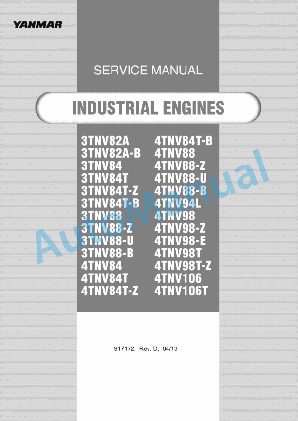
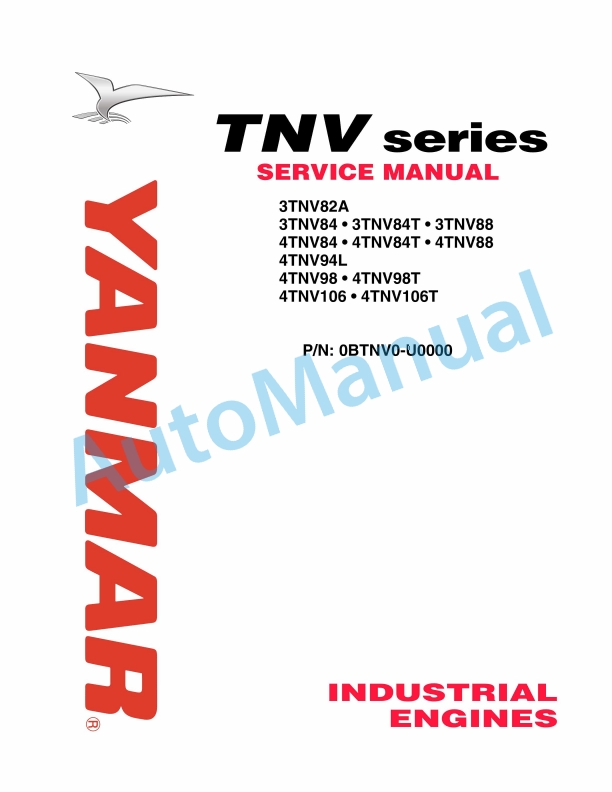
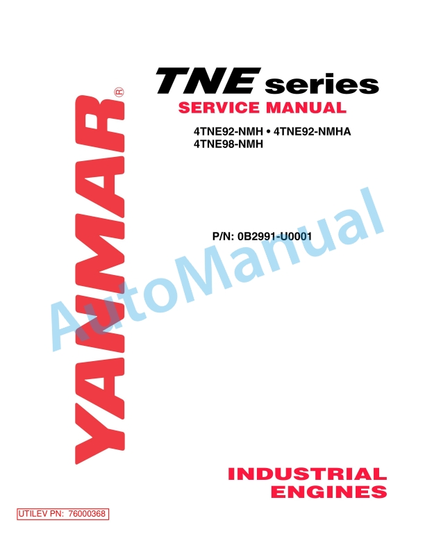
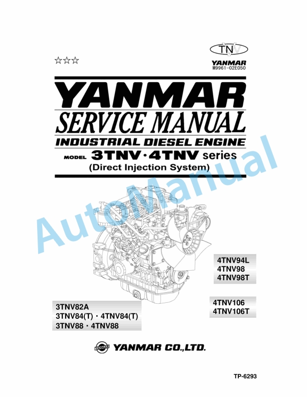
Model List:
- 4TNE92, 4TNE94L, 4TNE98 Industrial Engine
- 1. Introduction
- 2. Yanmar Warranties
- 2.1. Yanmar Limited Warranty
- 2.1.1. What is Covered by this Warranty
- 2.1.2. How Long is the Warranty Period
- 2.1.3. What the Engine Owner Must Do
- 2.1.4. To Locate an Authorized Yanmar Industrial Engine
- 2.1.5. Dealer or Distributor
- 2.1.6. What Yanmar Will Do
- 2.1.7. What is Not Covered by this Warranty
- 2.1.8. Warranty Limitations
- 2.1.9. Warranty Modifications
- 2.1.10. Questions
- 2.1.11. Customer Registration
- 2.2. Yanmar Co., Ltd. Limited Emission Control
- 2.3. System Warranty – USA Only
- 2.3.1. Your Warranty Rights and Obligations
- 2.3.1.1. California
- 2.3.1.2. All States
- 2.3.2. Manufacturers Warranty Period
- 2.3.3. Warranty Coverage
- 2.3.4. Warranted Systems / Parts Covered by this Warranty
- 2.3.5. Exclusions
- 2.3.6. Owners Warranty Responsibilities
- 2.4. Safety Statements
- 2.5. Safety Precautions
- 2.5.1. Before You Operate
- 2.5.2. During Operation and Maintenance
- 3. General Service Information
- 3.1. Component Identification
- 3.2. Location of Labels
- 3.3. EPA / ARB Emission Control Regulations – USA Only
- 3.4. Emission Control Labels
- 3.4.1. EPA / CARB Labels (Typical)
- 3.5. The 97/68/EC Directive Certified Engines
- 3.6. Engine Family
- 3.7. Function of Major Engine Components
- 3.8. Function of Cooling System Components
- 3.9. Diesel Fuel
- 3.9.1. Diesel Fuel Specifications
- 3.9.1.1. Additional Technical Fuel Requirements
- 3.9.1.2. Bio-Diesel Fuels
- 3.9.2. Filling The Fuel Tank
- 3.9.3. Priming the Fuel System
- 3.10. Engine Oil
- 3.10.1. Engine Oil Specifications
- 3.10.1.1. Service Categories
- 3.10.1.2. Definitions
- 3.10.1.3. Additional Technical Engine oil Requirements
- 3.10.2. Engine Oil Viscosity
- 3.10.3. Checking Engine Oil
- 3.10.4. Adding Engine Oil
- 3.10.5. Engine Oil Capacity (Typical)
- 3.11. Engine Coolant
- 3.11.1. Engine Coolant Specifications
- 3.11.1.1. Alternative Engine Coolant
- 3.11.1.2. Additional Technical Coolant Specifications
- 3.11.2. Filling Radiator With Engine Coolant
- 3.11.3. Engine Coolant Capacity (Typical)
- 3.12. Specifications
- 3.12.1. Description of Model Number
- 3.12.2. Engine Speed Specifications
- 3.12.3. Engine General Specifications
- 3.13. Principal Engine Specifications
- 3.13.1. NE92 EPA Tier2 Tier3
- 3.13.2. NE94L EPA Tier2
- 3.13.3. NE94L EPA Tier3
- 3.13.4. NE98 EPA Tier2
- 3.13.5. NE98 EPA Tier3
- 3.14. Engine Service Information
- 3.14.1. Engine Tuning
- 3.15. Tightening Torques for Standard Bolts and Nuts
- 3.16. Standard Torque Chart
- 3.17. Abbreviations and Symbols
- 3.17.1. Abbreviations
- 3.17.2. Symbols
- 3.18. Unit Conversions
- 3.18.1. Unit Prefixes
- 3.18.2. Units of Length
- 3.18.3. Units of Volume
- 3.18.4. Units of Mass
- 3.18.5. Units of Force
- 3.18.6. Units of Torque
- 3.18.7. Units of Pressure
- 3.18.8. Units of Power
- 3.18.9. Units of Temperature
- 4. Periodic Maintenance
- 4.1. Precautions
- 4.1.1. The Importance of Periodic Maintenance
- 4.1.2. Performing Periodic Maintenance
- 4.1.3. Yanmar Replacement Parts
- 4.1.4. Required EPA / ARB Maintenance – USA Only
- 4.1.5. EPA / ARB Installation Requirements – USA Only
- 4.1.6. Tightening Fasteners
- 4.2. Standard Torque Chart
- 4.3. Periodic Maintenance Schedule
- 4.4. Periodic Maintenance Procedures
- 4.4.1. Drain Fuel Filter / Water Separator
- 4.4.2. Check Fuel Hoses and Engine Coolant Hoses
- 4.4.3. Every 250 Hours of Operation
- 4.4.3.1. Check and Clean Radiator Fins
- 4.4.3.2. Check and Adjust Cooling Fan V-belt
- 4.4.3.3. Check Battery
- 4.4.3.4. Clean Air Cleaner Element
- 4.4.4. Every 500 Hours of Operation
- 4.4.4.1. Replace Engine Oil and Engine Oil Filter
- 4.4.4.2. Check and Adjust the Governor Lever and Engine Speed Control
- 4.4.5. Every 1000 Hours of Operation
- 4.4.5.1. Adjust Intake / Exhaust Valve Clearance
- 4.4.5.2. Clean Fuel Filter / Water Separator
- 4.4.5.3. Replace Fuel Filter
- 4.4.6. Every 2000 Hours of Operation
- 4.4.6.1. Replace Air Cleaner Element
- 4.4.6.2. Inspect Clean and Test Fuel Injectors
- 4.4.7. Every 4000 Hours of Operation
- 4.4.7.1. Drain, Flush, and Re-fill the Coolant System with New Coolant
- 4.4.7.2. Replace Fuel Hoses and Engine Coolant Hoses
- 4.5. Engine Service Information
- 4.5.1. Engine Body
- 4.5.1.1. Cylinder Head
- 4.5.1.2. Intake / Exhaust Valve and Guide
- 4.5.1.3. Valve Spring
- 4.5.1.4. Rocker Arm and Shaft
- 4.5.1.5. Push Rod
- 4.5.2. Gear Train and Camshaft
- 4.5.2.1. Camshaft
- 4.5.2.2. Idler Gear Shaft and Bushing
- 4.5.2.3. Backlash of Each Gear
- 4.5.2.4. Cylinder Block
- 4.5.2.5. Crankshaft
- 4.5.2.6. Thrust Bearing
- 4.5.2.7. Piston Ring
- 4.5.2.8. Connecting Rod
- 4.6. Engine Special Torque Chart
- 4.7. Special Service Tools
- 4.8. Measuring instruments
- 4.8.1. Before You Begin Servicing
- 4.9. Removal of Engine
- 4.9.1. Cylinder Head Components
- 4.9.2. Disassembly of Cylinder Head
- 4.9.2.1. Removal of Glow Plugs
- 4.9.2.2. Removal of Valve Cover
- 4.9.2.3. Removal of Rocker Arm Assembly
- 4.9.2.4. Disassembly of Rocker Arm Assembly
- 4.9.2.5. Removal of Cylinder Head
- 4.9.2.6. Removal of Intake / Exhaust Valves
- 4.9.2.7. Removal of Valve Guides
- 4.9.3. Cleaning of Cylinder Head Components
- 4.9.4. Inspection of Cylinder Head Components
- 4.9.4.1. Inspection of Push Rods
- 4.9.4.2. Inspection of Rocker Arm Assembly
- 4.9.4.3. Inspection of Valve Guides
- 4.9.4.4. Inspection of Cylinder Head
- 4.9.4.5. Inspection of Intake and Exhaust Valves
- 4.9.4.6. Inspection of Valve Springs
- 4.9.5. Assembly of Cylinder Head
- 4.9.5.1. Assembly of Valve Guides
- 4.9.5.2. Assembly of Intake and Exhaust Valves
- 4.9.5.3. Assembly of Cylinder Head
- 4.9.5.4. Assembly of Rocker Arm Assembly
- 4.9.5.5. Assembly of the Valve Cover
- 4.9.5.6. Assembly of Glow Plugs
- 4.10. Measuring and Adjusting Valve Clearance
- 4.10.1. Valve Clearance Measurement
- 4.10.2. Valve Clearance Adjustment
- 4.11. Drive Train and Camshaft Components
- 4.11.1. Disassembly of Drive Train and Camshaft Components
- 4.11.1.1. Removal of Oil Pan
- 4.11.1.2. Removal of Oil Sump Pump
- 4.11.1.3. Removal of Timing Gears
- 4.11.1.4. Removal of Pistons
- 4.11.1.5. Removal of Crankshaft
- 4.11.1.6. Removal of Camshaft
- 4.11.1.7. Removal of Gear Case
- 4.11.2. Inspection of Drive Train and Camshaft Components
- 4.11.2.1. Inspection of Cylinder Block
- 4.11.2.2. Inspection of Pistons
- 4.11.2.3. Inspection of Piston Pin
- 4.11.2.4. Inspection of Connecting Rod
- 4.11.2.5. Inspection of Tappets
- 4.11.2.6. Inspection of Crankshaft
- 4.11.2.7. Inspection of Camshaft
- 4.11.2.8. Inspection of Camshaft Bushings
- 4.11.2.9. Inspection of Idler Gear and Shaft
- 4.11.3. Honing and Boring
- 4.11.4. Assembly of Drive Train and Camshaft Components
- 4.11.4.1. Assembly of Pistons
- 4.11.4.2. Installation of Gear Case
- 4.11.4.3. Installation of Crankshaft
- 4.11.4.4. Installation of Pistons
- 4.11.4.5. Installation of Camshaft
- 4.11.4.6. Installation of Timing Gears
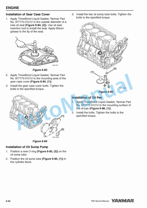
- 4.11.4.7. Installation of Gear Case Cover
- 4.11.4.8. Installation of Oil Sump Pump
- 4.11.4.9. Installation of Oil Pan
- 5. Fuel System
- 5.1. Fuel System Special Torque Chart
- 5.2. Measuring Instruments
- 5.3. Fuel System Components
- 5.4. Fuel System Diagram
- 5.5. Structure and Operation of Fuel Injection Pump
- 5.5.1. Overview
- 5.5.1.1. Governor
- 5.5.1.2. Feed Pump (Vane Type)
- 5.5.1.3. Regulating Valve
- 5.6. Plunger Operation
- 5.6.1. Process
- 5.6.1.1. Suction Process
- 5.6.1.2. Injection Process
- 5.6.1.3. End of Injection
- 5.6.1.4. Uniform Pressure Process
- 5.6.2. Reverse Rotation Prevention Mechanism
- 5.6.3. Fuel Injection Volume Adjustment Mechanism
- 5.6.4. Delivery Valve Assembly
- 5.6.5. Delivery Valve Holder with Damping Valve
- 5.7. All -Speed Governor
- 5.7.1. At Start of Engine
- 5.7.2. During Idling
- 5.7.3. At Full-Load Maximum Speed Control
- 5.7.4. At No-Load Maximum Speed Control
- 5.7.5. Full-Load Position Adjustment Mechanism
- 5.8. Structure and Operation of Timer
- 5.8.1. Standard Type Automatic Timer
- 5.8.2. Magnetic Valve (Stop Solenoid)
- 5.8.3. Cold Start Device (CSD)
- 5.8.3.1. Necessity of CSD
- 5.8.3.2. CSD Coupler Shape
- 5.8.3.3. Coolant Temperature Sensor
- 5.8.3.4. Controller External View (Optional)
- 5.8.3.5. Connecting Diagram
- 5.8.3.6. Actuation Chart
- 5.8.3.7. Function
- 5.8.3.8. Relay Characteristics
- 5.9. Before You Begin Servicing
- 5.10. Removal of Fuel Injection Pump
- 5.11. Installation of the Fuel Injection Pump
- 5.12. Checking / Adjustment of Fuel Injection Timing
- 5.13. Servicing the Fuel Injectors
- 5.13.1. Removal of the Fuel Injectors
- 5.13.2. Inspection and Testing of the Fuel Injectors
- 5.13.2.1. Test Procedure Using a Nozzle Tester
- 5.13.3. Judgement Criteria on Atomization Condition
- 5.13.3.1. Cleaning of Nozzle
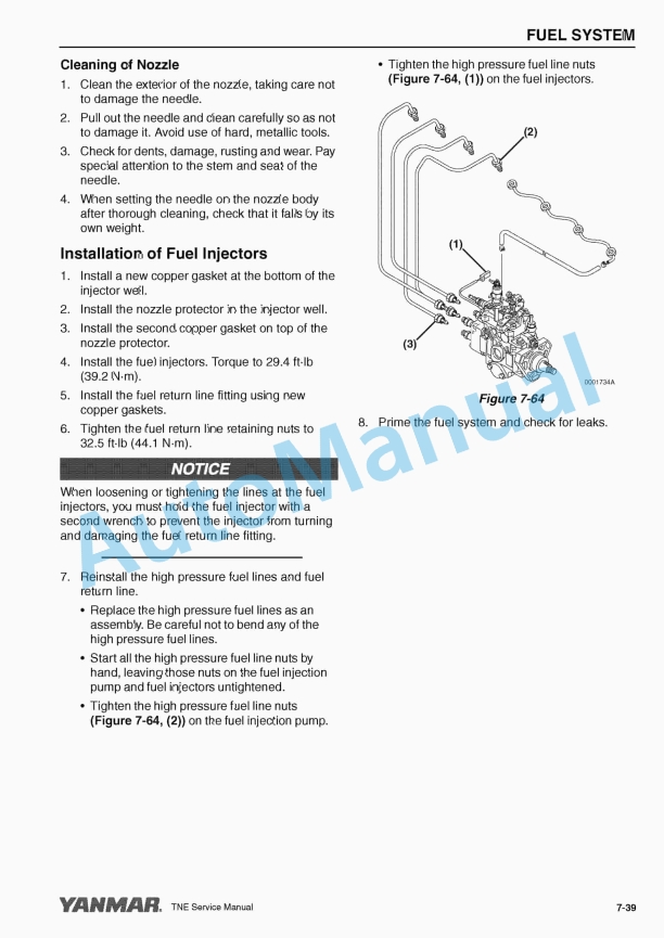
- 5.13.4. Installation of Fuel Injectors
- 6. Cooling System
- 6.1. Measuring Instruments
- 6.2. Cooling System Diagram
- 6.3. Engine Coolant Pump Components
- 6.4. Before You Begin Servicing
- 6.5. Engine Coolant System Check
- 6.6. Disassembly of Engine Coolant Pump
- 6.6.1. Disassembly of the Coolant Pumps
- 6.7. Cleaning and Inspection
- 6.7.1. Thermostat
- 6.7.2. Radiator Cap
- 6.8. Assembly of Engine Coolant Pump
- 6.8.1. Assembly of All Coolant Pump Models
- 7. Lubrication System
- 7.1. Oil Pump Service Information
- 7.1.1. Engine Oil Pressure – All Models
- 7.1.2. Outer Rotor Outside Clearance – All Models
- 7.1.3. Outer Rotor Side Clearance – All Models
- 7.1.4. Outer Rotor to Inner Rotor Tip Clearance – All Models
- 7.1.5. Rotor Shaft Clearance – All Models
- 7.2. Lubrication System Diagram
- 7.3. Checking Engine Oil Pressure
- 7.3.1. Oil Pump Components
- 7.3.2. Before You Begin Servicing
- 7.3.3. Disassembly of Oil Pump
- 7.3.4. Cleaning and Inspection
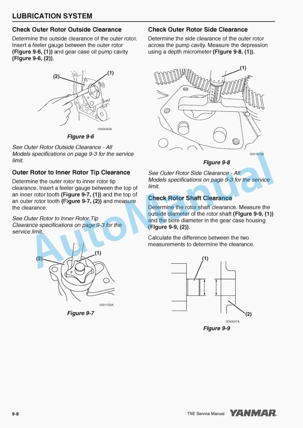
- 7.3.4.1. Check Outer Rotor Outside Clearance
- 7.3.4.2. Outer Rotor to Inner Rotor Tip Clearance
- 7.3.4.3. Check Outer Rotor Side Clearance
- 7.3.4.4. Check Rotor Shaft Clearance
- 7.3.5. Assembly of Oil Pump
- 8. Starter Motor
- 8.1. Starter Motor Service Information
- 8.2. Starter Motor Troubleshooting
- 8.3. Starter Motor Precautions
- 8.4. Starter Motor Servicing
- 8.4.1. Starter Motor Components
- 8.4.2. Before You Begin
- 8.4.3. Starter Motor Removal
- 8.4.4. Starter Motor Disassembly
- 8.4.5. Inspection
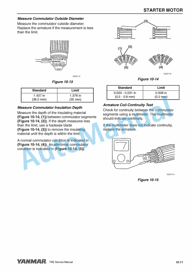
- 8.4.5.1. Armature
- 8.4.5.2. Field Coil
- 8.4.6. Brush Holder
- 8.4.6.1. Magnetic Switch
- 8.4.6.2. Pinion Clutch Assembly
- 8.4.7. Starter Motor Assembly
- 8.4.7.1. Check Pinion Projection Length
- 8.4.8. No Load Test
- 8.4.9. Starter Motor Installation
- 9. Alternator
- 9.1. Alternator Service Information
- 9.2. Alternator Troubleshooting
- 9.3. Alternator Precautions
- 9.4. Alternator Components
- 9.5. Alternator Servicing
- 9.5.1. Before You Begin Servicing
- 9.5.2. Removal of Alternator
- 9.5.3. Disassembly of Alternator
- 9.5.4. Inspection
- 9.5.4.1. Stator Coil
- 9.5.4.2. Rectifier
- 9.5.4.3. IC Regulator
- 9.5.5. Assembly of Brush Holder
- 9.5.6. Assembly of Alternator
- 9.5.7. Installation of Alternator
- 9.5.8. Bench Test
- 9.5.8.1. Test Wiring
- 9.5.8.2. Regulated Voltage Check
- 9.5.8.3. No Load Test
- 9.5.8.4. Output Test
- 10. Electric Wiring
- 10.1. Electric Wiring Precautions
- 10.2. Electrical Wire Resistance
- 10.3. Battery Cable Resistance
- 10.4. Electrical Wire Sizes – Voltage Drop
- 10.5. Conversion of AWG to European Standards
- 10.6. Electric Wiring Diagram (Reference)
- 11. Troubleshooting
- 11.1. Special Service Tools
- 11.2. Troubleshooting By Measuring Compression Pressure
- 11.2.1. Compression Pressure Measurement Method
- 11.2.2. Standard Compression Pressure
- 11.2.3. Engine Speed and Compression Pressure (Use for Reference)
- 11.2.4. Measured Value and Troubleshooting
- 11.3. Quick Reference Table For Troubleshooting
- 12. Back Cover

,%202GM(F)(L),%203GM(D)(F)(L),%203HM(F)(L)%20Engine%20Service%20Manual&url=https://pdfrepairmanual.com/docs/yanmar-1gm10l-2gmfl-3gmdfl-3hmfl-engine-service-manual/&media=https://pdfrepairmanual.com/wp-content/uploads/2026/01/yanmar-1gm10l-2gmfl-3gmdfl-3hmfl-engine-service-manual-1.jpg)


There are no reviews yet.