Yanmar B55W-1 Wheel Excavator Shop Manual
$30.00
- Type Of Manual: Shop Manual
- Number of Pages: 356
- Size: 103.6MB
- Format: PDF
Description
- 1. Table Of Contents
- 1.1. Wheel Excavator Safety
- 1.1.1. To the Operator of a Yanmar Excavator
- 1.1.2. General Safety Essentials
- 1.1.3. Location of Safety Labels
- 1.1.4. Summary of Safety Precautions for Lifting in Digging Mode
- 1.1.5. Unauthorized Modifications
- 1.1.6. General Hazard Information
- 1.1.7. Before Starting Engine
- 1.1.8. Machine Operation
- 1.1.9. Maintenance
- 1.1.10. Battery
- 1.1.11. Shipping and Transportation
- 1.1.12. Lifting With Sling
- 2. Specifications
- 2.1. Specifications for B55W-1
- 2.1.1. General Description
- 2.1.2. Component Locations
- 2.1.3. General Dimensions
- 2.1.4. Working Range
- 2.1.5. General Specifications
- 2.1.6. Weight Table
- 2.1.7. Working Attachments
- 3. General Maintenance
- 3.1. General Maintenance Procedures
- 3.1.1. Welding Precautions and Guidelines
- 3.1.2. Hydraulic System – General Precautions
- 3.1.3. Maintenance Service and Repair Procedure
- 3.1.4. Hydraulic System Cleanliness and Oil Leaks
- 3.1.5. Cleaning and Inspection
- 3.2. Standard Torques
- 3.2.1. Torque Values for Standard Metric Fasteners
- 3.2.2. Torque Values for Standard U.S. Fasteners
- 3.2.3. Type 8 Phosphate Coated Hardware
- 3.2.4. Torque Values for Hose Clamps
- 3.2.5. Torque Values for Split Flanges
- 3.2.6. Torque Wrench Extension Tools
- 4. Upper Structure
- 4.1. Counterweight
- 4.1.1. General
- 4.1.2. Removal
- 4.1.3. Installation
- 4.2. Fuel Transfer Pump
- 4.2.1. General Description
- 4.2.2. Troubleshooting
- 4.2.3. Replacement of Rotor and Vane
- 4.2.4. Replacement of Rear Cover
- 4.2.5. Replacement of Armature
- 4.3. Swing Bearing
- 4.3.1. Swing Bearing Maintenance
- 4.4. Swing Reduction Gearbox
- 4.4.1. General Description
- 4.4.2. Special Tools and Materials
- 4.4.3. Troubleshooting, Testing and Adjustment
- 4.4.4. Removal
- 4.4.5. Disassembly
- 4.4.6. Reassembly
- 4.4.7. Installation
- 5. Lower Structure and Chassis
- 5.1. Ram Lock Valve Operation
- 5.1.1. Theory of Operation
- 6. Engine and Drive Train
- 6.1. Drive Axle
- 6.1.1. Introduction
- 6.1.2. Special Tool
- 6.1.3. Trouble Shooting
- 6.1.4. Clark-Hurth Axle Identification
- 6.2. Air Conditioner
- 6.2.1. General Description
- 6.2.2. Refrigerant Circulation
- 6.2.3. Air-conditioning System Circuit Diagram
- 6.2.4. Troubleshooting
- 6.2.5. Weight of R134a Gas Used In Machines
- 6.2.6. Refrigerant System Repairs
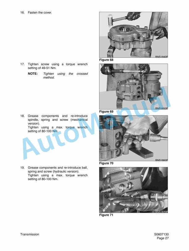
- 6.3. Transmission
- 6.3.1. Introduction
- 6.3.2. Maintenance and Lubricant
- 6.3.3. Diagrams of Reduction Unit and Exploded Views
- 6.3.4. Disassembly of Directly Flanged Reduction Gear 357
- 6.3.5. Removal of hydraulic gear control
- 6.3.6. Disassembly of Directly Flanged Reduction Gear 357
- 6.3.7. Assembly of Directly Flanged Reduction Gear 357
- 6.3.8. Installation of Hydraulic Gear Control
- 6.4. Drive Coupling (Main Pump)
- 6.4.1. Drive Coupling
- 6.4.2. Special Tools
- 6.4.3. Drive Coupling Installation
- 7. Hydraulics
- 7.1. Hydraulic System Troubleshooting, Testing and Adjustment
- 7.1.1. Hydraulic System
- 7.2. Accumulator
- 7.2.1. General Description
- 7.3. Center Joint (Swivel)
- 7.3.1. General Description
- 7.3.2. Troubleshooting, Testing and Adjustment
- 7.3.3. Disassembly
- 7.3.4. Reassembly
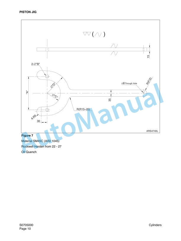
- 7.4. Cylinders
- 7.4.1. General Description
- 7.4.2. Special Tools and Materials
- 7.4.3. Disassembly
- 7.4.4. Assembly
- 7.5. Travel Motor
- 7.5.1. Sectional View
- 7.5.2. Seal Kits and Component Groups
- 7.5.3. Seal Kits and Component groups / Replace Seal Nut
- 7.5.4. Sealing the Drive Shaft
- 7.5.5. Sealing of the Control Parts
- 7.5.6. Sealing of the Relief Valve / Counter- Balance Valve
- 7.5.7. Spare Parts List Counter-Balance Valve
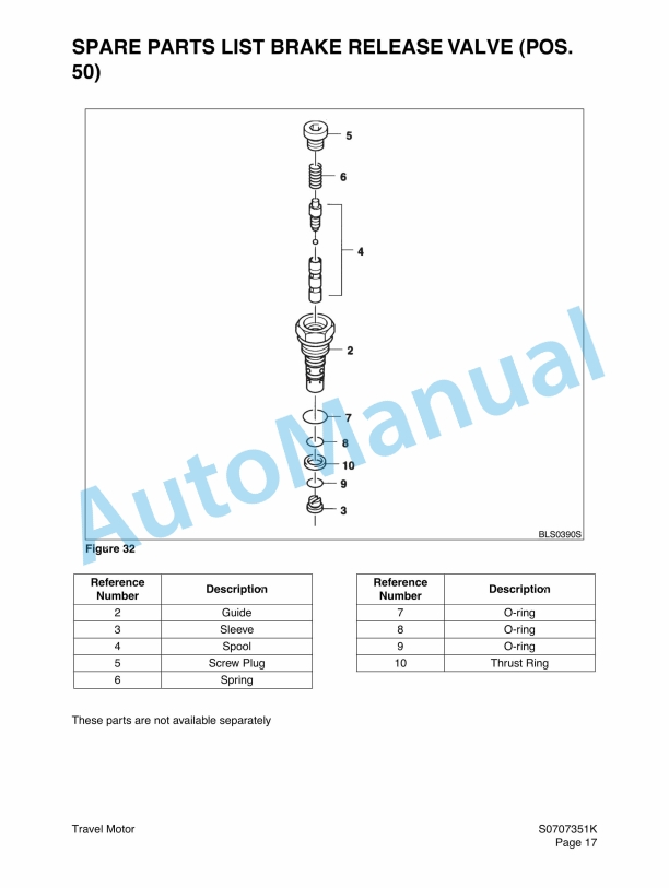
- 7.5.8. Spare Parts List Brake Release Valve (Pos. 50)
- 7.5.9. Disassembly of the Port Plate
- 7.5.10. Remove of the Positioning Piston
- 7.5.11. Remove Rotary Group
- 7.5.12. Exchanging of the rotary group
- 7.5.13. Inspection Notes
- 7.5.14. Rotary Group Assembly
- 7.5.15. Rotary Group Adjustment (see service information)
- 7.5.16. Assembly of the Port Plate
- 7.5.17. Tightening Torques
- 7.5.18. Safety Regulations
- 7.6. Swing Motor
- 7.6.1. Swing Motor
- 7.6.2. Troubleshooting
- 7.7. Main Pump
- 7.7.1. General Description
- 7.7.2. Operation Principle and Function of Components
- 7.7.3. Adjustment
- 7.7.4. Installation
- 7.7.5. Driving
- 7.7.6. Hydraulic Oil
- 7.7.7. Procedures for Test Operation
- 7.7.8. Maintenance and Protection
- 7.7.9. Checking Filters
- 7.7.10. Filter Replacement
- 7.7.11. Replacement of Hydraulic Oil
- 7.7.12. Hydraulic Fluid Leakage Check
- 7.7.13. Diagnosis of Troubles and Actions to be Taken
- 7.7.14. Disassembling and Reassembling hydraulic pump
- 7.8. Main Control Valve
- 7.8.1. Specifications
- 7.8.2. Internal Construction
- 7.8.3. Construction of Relief and Make-Up Valves
- 7.8.4. Operation
- 7.8.5. Disassembly
- 7.8.6. Assembly
- 7.8.7. Criteria for Maintenance
- 7.9. Pilot Control Valve (Work Lever / Joystick)
- 7.9.1. General Description
- 7.9.2. Special Tools
- 7.9.3. Disassembly
- 7.9.4. Reassembly
- 7.10. Hydraulic Schematic (B55W-1)
- 7.10.1. General Description
- 8. Electrical System
- 8.1. Electrical System
- 8.1.1. Overview
- 8.1.2. Electric Supply System
- 8.1.3. Engine Starting Circuit
- 8.1.4. Engine Preheating System
- 8.1.5. Engine Stop System
- 8.1.6. Charging System
- 8.1.7. Instrument System
- 8.2. Electrical Schematic (B55W-1)
- 8.2.1. General Description
- 9. Attachments
- 9.1. Bucket Tooth Inspection and Replacement
- 9.2. Bucket O-ring Replacement
- 9.3. Bucket Shimming Procedures
- 9.4. New Bucket Installation
- 9.5. Bucket Attachment, Removal and Reversal
- 9.6. Detaching the Bucket
- 9.7. Attaching The bucket
- 9.8. Reversing the Bucket
- 10. sm b55w-1 (c).pdf
- 10.1. Table Of Contents
- 10.1.1. Wheel Excavator Safety
- 10.2. Specifications
- 10.2.1. Specifications for B55W-1
- 10.3. General Maintenance
- 10.3.1. General Maintenance Procedures
- 10.3.2. Standard Torques
- 10.4. Upper Structure
- 10.4.1. Counterweight
- 10.4.2. Fuel Transfer Pump
- 10.4.3. Swing Bearing
- 10.4.4. Swing Reduction Gearbox
- 10.5. Lower Structure and Chassis
- 10.5.1. Ram Lock Valve Operation
- 10.6. Engine and Drive Train
- 10.6.1. Drive Axle
- 10.6.2. Air Conditioner
- 10.6.3. Transmission
- 10.6.4. Drive Coupling (Main Pump)
- 10.7. Hydraulics
- 10.7.1. Hydraulic System Troubleshooting, Testing and Adjustment
- 10.7.2. Accumulator
- 10.7.3. Center Joint (Swivel)
- 10.7.4. Cylinders
- 10.7.5. Travel Motor
- 10.7.6. Swing Motor
- 10.7.7. Main Pump
- 10.7.8. Main Control Valve
- 10.7.9. Pilot Control Valve (Work Lever / Joystick)
- 10.7.10. Hydraulic Schematic (B55W-1)
- 10.8. Electrical System
- 10.8.1. Electrical System
- 10.8.2. Electrical Schematic (B55W-1)
- 10.9. Attachments
- 10.9.1. Bucket Tooth Inspection and Replacement
- 10.9.2. Bucket O-ring Replacement
- 10.9.3. Bucket Shimming Procedures
- 10.9.4. New Bucket Installation
- 10.9.5. Bucket Attachment, Removal and Reversal
- 10.9.6. Detaching the Bucket
- 10.9.7. Attaching The bucket
- 10.9.8. Reversing the Bucket
- 11. sm b55w-1 (d).pdf
- 11.1. Table Of Contents
- 11.1.1. Wheel Excavator Safety
- 11.2. Specifications
- 11.2.1. Specifications for B55W-1
- 11.3. General Maintenance
- 11.3.1. General Maintenance Procedures
- 11.3.2. Standard Torques
- 11.4. Upper Structure
- 11.4.1. Counterweight
- 11.4.2. Fuel Transfer Pump
- 11.4.3. Swing Bearing
- 11.4.4. Swing Reduction Gearbox
- 11.5. Lower Structure and Chassis
- 11.5.1. Ram Lock Valve Operation
- 11.6. Engine and Drive Train
- 11.6.1. Drive Axle
- 11.6.2. Air Conditioner
- 11.6.3. Transmission
- 11.6.4. Drive Coupling (Main Pump)
- 11.7. Hydraulics
- 11.7.1. Hydraulic System Troubleshooting, Testing and Adjustment
- 11.7.2. Accumulator
- 11.7.3. Center Joint (Swivel)
- 11.7.4. Cylinders
- 11.7.5. Travel Motor
- 11.7.6. Swing Motor
- 11.7.7. Main Pump
- 11.7.8. Main Control Valve
- 11.7.9. Pilot Control Valve (Work Lever / Joystick)
- 11.7.10. Hydraulic Schematic (B55W-1)
- 11.8. Electrical System
- 11.8.1. Electrical System
- 11.8.2. Electrical Schematic (B55W-1)
- 11.9. Attachments
- 11.9.1. Bucket Tooth Inspection and Replacement
- 11.9.2. Bucket O-ring Replacement
- 11.9.3. Bucket Shimming Procedures
- 11.9.4. New Bucket Installation
- 11.9.5. Bucket Attachment, Removal and Reversal
- 11.9.6. Detaching the Bucket
- 11.9.7. Attaching The bucket
- 11.9.8. Reversing the Bucket
- 12. sm b55w-1 (e).pdf
- 12.1. Table Of Contents
- 12.1.1. Wheel Excavator Safety
- 12.2. Specifications
- 12.2.1. Specifications for B55W-1
- 12.3. General Maintenance
- 12.3.1. General Maintenance Procedures
- 12.3.2. Standard Torques
- 12.4. Upper Structure
- 12.4.1. Counterweight
- 12.4.2. Fuel Transfer Pump
- 12.4.3. Swing Bearing
- 12.4.4. Swing Reduction Gearbox
- 12.5. Lower Structure and Chassis
- 12.5.1. Ram Lock Valve Operation
- 12.6. Engine and Drive Train
- 12.6.1. Drive Axle
- 12.6.2. Air Conditioner
- 12.6.3. Transmission
- 12.6.4. Drive Coupling (Main Pump)
- 12.7. Hydraulics
- 12.7.1. Hydraulic System Troubleshooting, Testing and Adjustment
- 12.7.2. Accumulator
- 12.7.3. Center Joint (Swivel)
- 12.7.4. Cylinders
- 12.7.5. Travel Motor
- 12.7.6. Swing Motor
- 12.7.7. Main Pump
- 12.7.8. Main Control Valve
- 12.7.9. Pilot Control Valve (Work Lever / Joystick)
- 12.7.10. Hydraulic Schematic (B55W-1)
- 12.8. Electrical System
- 12.8.1. Electrical System
- 12.8.2. Electrical Schematic (B55W-1)
- 12.9. Attachments
- 12.9.1. Bucket Tooth Inspection and Replacement
- 12.9.2. Bucket O-ring Replacement
- 12.9.3. Bucket Shimming Procedures
- 12.9.4. New Bucket Installation
- 12.9.5. Bucket Attachment, Removal and Reversal
- 12.9.6. Detaching the Bucket
- 12.9.7. Attaching The bucket
- 12.9.8. Reversing the Bucket
- 13. sm b55w-1 (f).pdf
- 13.1. Table Of Contents
- 13.1.1. Wheel Excavator Safety
- 13.2. Specifications
- 13.2.1. Specifications for B55W-1
- 13.3. General Maintenance
- 13.3.1. General Maintenance Procedures
- 13.3.2. Standard Torques
- 13.4. Upper Structure
- 13.4.1. Counterweight
- 13.4.2. Fuel Transfer Pump
- 13.4.3. Swing Bearing
- 13.4.4. Swing Reduction Gearbox
- 13.5. Lower Structure and Chassis
- 13.5.1. Ram Lock Valve Operation
- 13.6. Engine and Drive Train
- 13.6.1. Drive Axle
- 13.6.2. Air Conditioner
- 13.6.3. Transmission
- 13.6.4. Drive Coupling (Main Pump)
- 13.7. Hydraulics
- 13.7.1. Hydraulic System Troubleshooting, Testing and Adjustment
- 13.7.2. Accumulator
- 13.7.3. Center Joint (Swivel)
- 13.7.4. Cylinders
- 13.7.5. Travel Motor
- 13.7.6. Swing Motor
- 13.7.7. Main Pump
- 13.7.8. Main Control Valve
- 13.7.9. Pilot Control Valve (Work Lever / Joystick)
- 13.7.10. Hydraulic Schematic (B55W-1)
- 13.8. Electrical System
- 13.8.1. Electrical System
- 13.8.2. Electrical Schematic (B55W-1)
- 13.9. Attachments
- 13.9.1. Bucket Tooth Inspection and Replacement
- 13.9.2. Bucket O-ring Replacement
- 13.9.3. Bucket Shimming Procedures
- 13.9.4. New Bucket Installation
- 13.9.5. Bucket Attachment, Removal and Reversal
- 13.9.6. Detaching the Bucket
- 13.9.7. Attaching The bucket
- 13.9.8. Reversing the Bucket



,%202GM(F)(L),%203GM(D)(F)(L),%203HM(F)(L)%20Engine%20Service%20Manual&url=https://pdfrepairmanual.com/docs/yanmar-1gm10l-2gmfl-3gmdfl-3hmfl-engine-service-manual/&media=https://pdfrepairmanual.com/wp-content/uploads/2026/01/yanmar-1gm10l-2gmfl-3gmdfl-3hmfl-engine-service-manual-1.jpg)

(C)(M)E%20Service%20Manual&url=https://pdfrepairmanual.com/docs/yanmar-3jh4bcme-service-manual/&media=https://pdfrepairmanual.com/wp-content/uploads/2026/01/yanmar-3jh4bcme-service-manual-1.jpg)
There are no reviews yet.