
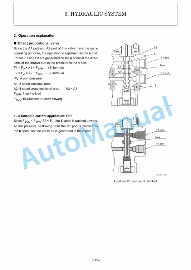
Description
-
Model List:
- SV86-7, SV100-7 Mini Excavator
- 1. SV86-7 SV100-7 SERVICE MANUAL.pdf
- 1.1. Foreword
- 1.2. CONTENTS
- 1.3. General Cautions for Maintenance Work
- 1.3.1. Correct Work
- 1.3.2. Safety Precautions
- 1.3.3. Preparations
- 1.3.4. Cautions for Disassembly and Reassembly
- 1.3.5. Cautions for Removal and Installation of Hydraulic Equipment
- 1.3.6. Cautions for Removal and Installation of Hydraulic Piping
- 1.3.7. Cautions for Handling Seals
- 1.3.8. Correct Installation of Hydraulic Hose
- 1.3.9. Specifications of Hydraulic Hose
- 1.3.10. Air Release of Hydraulic Equipment
- 1.4. Technical Data
- 1.4.1. Specifications
- 1.4.1.1. Standard arm type
- 1.4.1.2. Long arm type
- 1.4.1.3. Arti-boom type
- 1.4.2. Outline Drawing and Working Area
- 1.4.2.1. Standard arm type
- 1.4.2.2. Long arm type
- 1.4.2.3. Arti-boom type
- 1.4.3. Weight List of Main Parts
- 1.4.4. Lifting Capacity List
- 1.4.4.1. SV86-7
- 1.4.4.2. SV100-7
- 1.4.5. Specifications for Attachment
- 1.4.5.1. SV86-7
- 1.4.5.2. SV100-7
- 1.4.6. Periodic Inspection and Servicing
- 1.4.7. Fuel, Lube Oil and Grease Recommended
- 1.4.8. Hydraulic Circuit Schematic
- 1.4.8.1. SV86-7
- 1.4.8.2. SV86-7 (Arti-boom spec.)
- 1.4.8.3. SV100-7
- 1.4.8.4. SV100-7 (Arti-boom spec.)
- 1.4.9. Wiring Diagram
- 1.5. Service Standards
- 1.5.1. Machine Performance
- 1.5.2. Engine
- 1.5.3. Undercarriage
- 1.5.3.1. Rubber Crawler Specifications
- 1.5.3.2. Steel Crawler Specifications
- 1.5.3.3. Common Specifications of Steel Rubber Crawlers
- 1.5.4. Controls
- 1.5.5. Hydraulic Equipment
- 1.5.5.1. Hydraulic Cylinders
- 1.5.6. Implement
- 1.5.6.1. Front Attachments
- 1.5.6.2. Blade Moving Device
- 1.5.7. List of Tightening Torque
- 1.5.7.1. Special management parts for main machine
- 1.5.7.2. Engine
- 1.5.7.3. Tightening Torque for General Bolts and Nuts
- 1.5.7.4. Hydraulic Fitting
- 1.5.7.5. Solenoids tightening torque
- 1.5.7.6. Breathers tightening torque
- 1.5.8. Pressure Adjustment
- 1.5.8.1. Relief Valves
- 1.5.8.2. Swing Brake Valve
- 1.5.8.3. Cut-off Valve
- 1.5.8.4. Accumulator
- 1.6. Engine
- 1.6.1. INTRODUCTION
- 1.6.2. YANMAR WARRANTIES
- 1.6.2.1. YANMAR LIMITED WARRANTY
- 1.6.2.2. YANMAR POWER TECHNOLOGY CO., LTD. LIMITED EMISSION CONTROL SYSTEMWARRANTY
- 1.6.3. SAFETY
- 1.6.3.1. SAFETY STATEMENTS
- 1.6.3.2. SAFETY PRECAUTIONS
- 1.6.4. PRODUCT OVERVIEW
- 1.6.4.1. YANMAR TNV/TN ENGINE FEATURES AND APPLICATIONS
- 1.6.4.2. COMPONENT IDENTIFICATION
- 1.6.4.3. LOCATION OF LABELS
- 1.6.4.4. EMISSION CONTROL REGULATIONS
- 1.6.4.5. EMISSION CONTROL LABELS
- 1.6.4.6. ENGINE FAMILY
- 1.6.4.7. FUNCTION OF MAJOR ENGINE COMPONENTS
- 1.6.4.8. FUNCTION OF COOLING SYSTEM COMPONENTS
- 1.6.4.9. ELECTRONIC CONTROL SYSTEM
- 1.6.4.10. INSTALLATION POSITION OF SENSORS FOR ELECTRONIC CONTROL SYSTEM
- 1.6.4.11. GAUGES AND INDICATORS
- 1.6.5. BEFORE YOU OPERATE
- 1.6.5.1. DIESEL FUEL
- 1.6.5.2. ENGINE LUBRICATING OIL
- 1.6.5.3. ENGINE COOLANT
- 1.6.5.4. DAILY CHECKS
- 1.6.6. ENGINE OPERATION
- 1.6.6.1. STARTING ENGINE
- 1.6.6.2. CHECKING THE ENGINE DURING OPERATION
- 1.6.6.3. SHUTTING DOWN THE ENGINE
- 1.6.7. PERIODIC MAINTENANCE
- 1.6.7.1. PRECAUTIONS
- 1.6.7.2. STANDARD TORQUE CHART
- 1.6.7.3. PERIODIC MAINTENANCE SCHEDULE
- 1.6.7.4. PERIODIC MAINTENANCE PROCEDURES
- 1.6.8. TROUBLESHOOTING
- 1.6.8.1. TROUBLESHOOTING CHART
- 1.6.8.2. TROUBLESHOOTING INFORMATION
- 1.6.8.3. TROUBLESHOOTING OF ELECTRONIC CONTROL SYSTEM
- 1.6.8.4. TROUBLESHOOTING FOR ELECTRONIC CONTROL SYSTEM
- 1.6.9. LONG-TERM STORAGE
- 1.6.9.1. BEFORE YOU PLACE THE ENGINE IN LONG-TERM STORAGE
- 1.6.9.2. RETURNING THE ENGINE TO SERVICE
- 1.6.10. SPECIFICATIONS
- 1.6.10.1. GENERAL
- 1.6.10.2. PRINCIPAL ENGINE SPECIFICATIONS
- 1.7. Electric System
- 1.7.1. Electric Equipment of Machine
- 1.7.1.1. Parts Layout of Electrical Equipment
- 1.7.1.2. LCD Monitor and Alarm Systems
- 1.7.2. Circuit Description of Engine Start Stop and battery charge
- 1.7.3. Engine ECU (engine controller)
- 1.7.3.1. Outline
- 1.7.3.2. Control Functions
- 1.7.4. Hydraulic ECU (Pump Controller)
- 1.7.4.1. Outline
- 1.7.4.2. Engine Control
- 1.7.4.3. Speed Sensing Horsepower Limit Control
- 1.7.4.4. Load Sensing Gain Control (Pump Flow Rate Control)
- 1.7.5. Camera adjustment
- 1.7.6. Error Code
- 1.7.7. Battery
- 1.7.7.1. Generality
- 1.7.7.2. Maintenance
- 1.8. Hydraulic System
- 1.8.1. Outline
- 1.8.1.1. Control Valve Operation
- 1.8.1.2. Additional Operation of Control Valve
- 1.8.2. Circuit Operation
- 1.8.2.1. Boom
- 1.8.2.2. Arm
- 1.8.2.3. Bucket
- 1.8.2.4. Simultaneous Implement Operations
- 1.8.2.5. Swing
- 1.8.2.6. Boom Swing
- 1.8.2.7. Arti-boom (Arti-boom spec.)
- 1.8.2.8. Blade
- 1.8.2.9. Travel
- 1.8.2.10. Non-deviation Travel (Example Simultaneousoperation of traveling forward,boom raising, and arm excavation)
- 1.8.2.11. Hydraulic AUX1
- 1.8.2.12. Hydraulic AUX2
- 1.8.2.13. Hydraulic AUX3 (AUX3 Spec.)
- 1.8.2.14. Auto Deceleration
- 1.8.3. Hydraulic Pump
- 1.8.3.1. Main Specifications and Appearance
- 1.8.3.2. Basic Configuration and Operation Theory
- 1.8.3.3. Part Names
- 1.8.3.4. Disassembly and Reassembly
- 1.8.3.5. Service Standards
- 1.8.3.6. Troubleshooting
- 1.8.4. Control Valve
- 1.8.5. Pilot Valve
- 1.8.5.1. Remote Control Valve
- 1.8.5.2. Travel Pilot Valve
- 1.8.5.3. Blade valve (Swing valve)
- 1.8.6. Swing Motor
- 1.8.6.1. Overview
- 1.8.6.2. Description of Functions and Operation
- 1.8.6.3. Precautions for Handling
- 1.8.6.4. Troubleshooting
- 1.8.6.5. Employment Tool
- 1.8.6.6. Disassembly Procedure
- 1.8.6.7. Assembly Procedure
- 1.8.6.8. Quality Check After Reassembly.
- 1.8.7. Travel Motor (SV86-7)
- 1.8.7.1. Product Overview
- 1.8.7.2. External Dimensions
- 1.8.7.3. Basic Configuration and Drawing
- 1.8.7.4. Operating Description
- 1.8.7.5. Troubleshooting
- 1.8.7.6. Service outline
- 1.8.7.7. Disassembly
- 1.8.7.8. Service Standard
- 1.8.7.9. Assembly
- 1.8.7.10. Performance Confirmation Test
- 1.8.8. Travel Motor (SV100-7)
- 1.8.8.1. Product Overview
- 1.8.8.2. External Dimensions and Circuit Diagram
- 1.8.8.3. Basic Configuration and Drawing
- 1.8.8.4. Operating Description
- 1.8.8.5. Procedures for Replacement of Gear Oil
- 1.8.8.6. Troubleshooting
- 1.8.8.7. Storage of the Travel Unit
- 1.8.8.8. Disposal Methods
- 1.8.8.9. Outline of Services
- 1.8.8.10. Disassembly
- 1.8.8.11. Service Standard
- 1.8.8.12. Assembly
- 1.8.8.13. Performance Confirmation Test
- 1.8.9. Pump Control Proportional Solenoid Valve
- 1.8.10. Arti-boom check valve
- 1.8.11. Solenoid Valve
- 1.8.12. Quick Coupler Solenoid Valve
- 1.8.13. AUX Solenoid
- 1.8.14. Safety Valve
- 1.8.15. High/Low switching Valve
- 1.8.16. Hydraulic tank breather
- 1.9. Adjustment and Repair
- 1.9.1. Hood and Weight
- 1.9.1.1. Removal and installation of hood
- 1.9.1.2. Removal and installation of additional weights (additional weights Spec.)
- 1.9.1.3. Removal and installation of weights
- 1.9.2. Engine and Electrical Components
- 1.9.2.1. Removal and installation of engine
- 1.9.2.2. Removal and installation of the starting motor
- 1.9.2.3. Removal and installation of the radiator and oil cooler
- 1.9.2.4. Removal and installation of the fan belt and compressor belt
- 1.9.2.5. Removal and installation of engine ECU
- 1.9.2.6. Removal and installation of hydraulic ECU
- 1.9.2.7. Removal and installation of diesel particulate filter (DPF)
- 1.9.3. Undercarriage
- 1.9.3.1. Outline
- 1.9.3.2. Main parts
- 1.9.3.3. Precautions for assembly
- 1.9.3.4. Removal and Reinstallation of Crawler
- 1.9.3.5. Disassembly and Reassembly of steel crawler
- 1.9.3.6. Removal and Reinstallation of Travel Motor
- 1.9.3.7. Disassembly and Reassembly of Idler
- 1.9.3.8. Disassembly and Reassembly of Track Roller
- 1.9.3.9. Disassembly and Reassembly of Carrier Roller
- 1.9.3.10. Installation of Floating Seal
- 1.9.4. Control unit
- 1.9.4.1. Operation lever
- 1.9.4.2. Travel lever
- 1.9.5. Swing Bearing
- 1.9.5.1. Removal and Reinstallation of Swing Bearing
- 1.9.6. Hydraulic device
- 1.9.6.1. Removal and installation of hydraulic pump
- 1.9.6.2. Removal and installation of control valves
- 1.9.6.3. Removal and installation of pilot valves (L, R)
- 1.9.6.4. Removal and installation of blade pilot valve
- 1.9.6.5. Removal and installation of travel pilot valve
- 1.9.6.6. Removal and installation of swing pilot valve
- 1.9.6.7. Removal and installation of arti-boom pilot valve
- 1.9.6.8. Removal and installation of cut-off valve and accumulator
- 1.9.6.9. Removal and Reinstallation of AUX Solenoid Valve
- 1.9.6.10. Removal and Reinstallation of AUX2 Solenoid Valve
- 1.9.6.11. Removal and Reinstallation of AUX3 Solenoid Valve (AUX3 Spec.)
- 1.9.6.12. Removal and installation of pump control proportional valve
- 1.9.6.13. Removal and installation of blade hold valve
- 1.9.6.14. Removal and installation of line filter
- 1.9.6.15. Removal and installation of swing motor
- 1.9.6.16. Removal and Reinstallation of Swivel Joint
- 1.9.6.17. Disassembly and Reassembly of Swivel Joint
- 1.9.6.18. Hydraulic cylinder disassembly and assembly
- 1.9.6.19. Reservoir tank
- 1.9.6.20. Hydraulic piping diagram
- 1.9.7. Implement
- 1.9.7.1. Removal and installation of implements
- 1.9.7.2. Removal and Reinstallation of Implement (Arti-boom spec.)
- 1.9.8. Cabin
- 1.9.8.1. Removal and installation of cabin
- 1.9.8.2. Cabin disassembly and assembly
- 1.9.8.3. Procedures for replacement of bonded glass
- 1.9.9. Air conditioner
- 1.9.9.1. Removal and installation of air conditioner
- 1.10. Troubleshooting
- 1.10.1. Non-breakdowns
- 1.10.1.1. Natural Release of Bucket
- 1.10.1.2. Discontinuous Arm and Bucket Movement
- 1.10.1.3. Thermal Shock of Travel Motor
- 1.10.1.4. Elongation of Boom Swing Cylinder on 60 degrees Swing
- 1.10.1.5. Time Lag on Travel Speed Switching
- 1.10.1.6. Fluctuation in Oil Level of Hydraulic Oil Tank due to Temperature Change
- 1.10.2. Quick Reference Table for Troubleshooting
- 1.11. Colophon
- 1.12. APPENDIX


,%202GM(F)(L),%203GM(D)(F)(L),%203HM(F)(L)%20Engine%20Service%20Manual&url=https://pdfrepairmanual.com/docs/yanmar-1gm10l-2gmfl-3gmdfl-3hmfl-engine-service-manual/&media=https://pdfrepairmanual.com/wp-content/uploads/2026/01/yanmar-1gm10l-2gmfl-3gmdfl-3hmfl-engine-service-manual-1.jpg)


,%202GM(F)(L),%203GM(D)(F)(L),%203HM(F)(L)%20Marine%20Diesel%20Engine%20Service%20Manual&url=https://pdfrepairmanual.com/docs/yanmar-1gm10l-2gmfl-3gmdfl-3hmfl-marine-diesel-engine-service-manual/&media=https://pdfrepairmanual.com/wp-content/uploads/2026/01/yanmar-1gm10l-2gmfl-3gmdfl-3hmfl-marine-diesel-engine-service-manual-1.jpg)
There are no reviews yet.