

Description
-
Model List:
- PC3400-11M0 Hydraulic Excavator
- 1. COVER
- 2. FOREWORD
- 2.1. Foreword
- 2.2. Precautions for field assembly
- 2.2.1. How to do work
- 2.2.2. Preparation and check of protective gear, slings and tools
- 2.2.3. Check during actual work
- 2.3. Disposal of removed parts
- 3. SAFETY
- 3.1. Safety information
- 3.2. Overview
- 3.2.1. Normal operations
- 3.2.2. Regular maintenance
- 3.2.3. Troubleshooting, adjustments and repair
- 3.2.4. Additional safety precautions
- 3.3. Sound pressure and vibration levels in the operators cab.
- 3.3.1. Sound
- 3.3.2. Vibration
- 3.4. General precautions common to operation on the excavator
- 3.4.1. Understanding the excavator
- 3.4.2. Precautions before starting operation on the excavator
- 3.4.3. Preparations for safe operation
- 3.4.4. Fire prevention
- 3.4.5. Precautions when getting on or off the excavator
- 3.4.6. Burn prevention
- 3.4.7. Precautions when cleaning cab glass
- 3.4.8. Precautions related to protective structures
- 3.4.9. Precautions related to airbourne and ejected debris
- 3.4.10. Electromagnetic compatibility (EMC)
- 3.4.11. Precautions at jobsite
- 3.4.12. Starting motor
- 3.4.13. Operation
- 3.5. Precaution for maintenance
- 3.5.1. General precautions
- 3.5.2. Precautions for inspection and maintenance
- 3.5.3. Precautions with high pressure fluid
- 3.6. Additional safety information for troubleshooting and adjustments
- 3.6.1. Inspection of the hydraulic system
- 3.6.2. Two workers only when the excavator is running during adjustments
- 3.6.3. Areas of potential danger around the excavator
- 3.7. Special safety equipment
- 3.7.1. Front guard protective structure FOPS for operators cab
- 3.7.2. Object handling
- 3.7.3. Lighting
- 3.7.4. Warning beacon
- 3.7.5. Safety harness in conformity with en 361 (european standard)
- 3.8. Additional safety precautions for assembly
- 3.8.1. When assembling the excavator
- 3.8.2. When disassembling the excavator
- 3.8.3. When transporting the disassembled excavator
- 4. GENERAL
- 4.1. General
- 4.1.1. Delivery of the excavator
- 4.1.2. Assembling the excavator
- 4.1.3. Lifting and transportation
- 4.1.4. Electrical energy
- 4.1.5. Electromagnetic compatibility (EMC)
- 4.1.6. Monitoring system of the machine
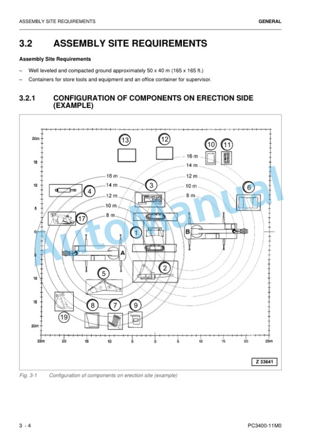
- 4.2. Assembly site requirements
- 4.2.1. Configuration of components on erection side (example)
- 4.2.2. Required cranes
- 4.2.3. Manpower / Assembly time
- 4.2.4. Tools and equipment for assembly
- 4.3. Standard application torque chart
- 4.3.1. Metric standard thread
- 4.3.2. Metric fine thread
- 4.4. Special Tightening Torques
- 4.5. Torque for flange Joints
- 4.6. Tightening Torque for hydraulic hose connecting nut
- 4.7. General installation procedures for hydraulic hose lines
- 4.8. General installation instructions for attachment pins
- 4.8.1. Preparations for assembly
- 4.9. Transportation Postures
- 5. ASSEMBLY SEQUENCE
- 5.1. Assemble sequence
- 5.1.1. Assembly sequence under consideration of the excavators stability
- 5.2. Assemble the undercarriage (center body, track frames)
- 5.2.1. Preparations before working
- 5.2.2. Attach Center body to Track Frames
- 5.2.3. Special hydraulic torque wrench
- 5.2.4. Connect Hydraulic Lines to the travel motors
- 5.2.5. Connect Hydraulic Lines to the travel motors
- 5.2.6. Hydraulic track tensioning system
- 5.2.7. Final Assembly of undercarriage
- 5.3. Assemble the main valve block assembly (if equipped)
- 5.4. Assemble the floating valve block assembly (for FRONT SHOVEL (FS))
- 5.5. Assemble the superstructure platform
- 5.6. Assemble the machine house assembly
- 5.6.1. Assemble the air cleaner Assembly
- 5.6.2. Assemble the exhaust muffler assembly
- 5.6.3. Assemble the handrails
- 5.6.4. Connect service center
- 5.7. Assemble the L.H. platform
- 5.8. Assemble hydraulically operated stairway
- 5.9. Assemble the machine house L.H. platform
- 5.10. Assemble the cab base
- 5.10.1. Assemble the cab base walks and attachments
- 5.11. Assemble the operators cab
- 5.12. Assemble the fuel tank top platform
- 5.13. Assemble the lubrication pump station
- 5.14. Assemble the hydraulic oil tank
- 5.14.1. Assemble the platform between machine house and hydraulic oil tank
- 5.15. Assemble the superstructure floor frame
- 5.16. Assemble the machine house R.H. platform
- 5.17. Assemble the hydraulic oil tank R.H. platform
- 5.18. Assemble the emergency escape ladder at the machine house
- 5.19. Assemble the oil cooler assembly
- 5.20. Preassemble for backhoe (BH) BOOM
- 5.20.1. Preparatory work
- 5.20.2. Assemble the boom cylinders
- 5.20.3. Assemble the stick cylinders
- 5.21. Preassembly of front shovel boom
- 5.22. Assemble the counterweight
- 5.23. Install the Preassembled boom at the superstructure
- 5.23.1. Install the boom cylinder at the superstructure
- 5.24. Connect the components and piping around the boom foot
- 5.25. Prechecks before engine start
- 5.25.1. Prechecks prior to initial start up
- 5.25.2. Filling and bleeding the hydraulic system
- 5.26. Install the stick at the boom (for backhoe (BH))
- 5.27. Connect the stick cylinders and stick (for backhoe (BH))
- 5.28. Connect the components and piping around the stick (for backhoe (BH))
- 5.29. Bleeding the bucket cylinder
- 5.30. Assemble the bucket (for backhoe (BH))
- 5.31. Assembly front shovel attachment
- 5.31.1. Attaching the bucket cylinders to the boom
- 5.31.2. Attaching the stick to the boom
- 5.31.3. Connecting hose lines from main valve block to boom
- 5.31.4. Connecting hose lines from boom to boom cylinders
- 5.31.5. Connecting hose lines from boom to stick cylinders
- 5.31.6. Connecting hose lines from stick to bucket cylinders
- 5.31.7. Connecting stick cylinders to the stick
- 5.32. Bleed air from hydraulic oil tank
- 5.33. Bleed air from track tensioning system
- 5.34. Bleed slew circuit
- 5.35. Bleed air from track system
- 6. DISASSEMBLY OF THE EXCAVATOR
- 6.1. Disassembly sequence of backhoe excavators
- 6.2. Disassembly sequence of front shovel
- 6.3. Safety precautions for disassembling the excavator
- 6.3.1. Disposal of the waste material
- 7. FINAL CHECKS AND ADJUSTMENTS
- 7.1. Commissioning check list
- 7.2. Adjustment of automatic lubrication systems
- 7.2.1. Setting of pause time and grease injector output (continued)
- 7.3. Charging air conditioner with refrigerant
- 7.4. Perform the PM Clinic commissioning procedure according to the PM Clinic manual
- 7.4.1. Visual inspection
- 7.4.2. Traveling instructions
- 7.5. Handling of documentation after assembly and commissioning
- 8. ORBCOMM INITIALIZATION
- 8.1. PC configuration tool for KOMTRAX Plus / ORBCOMM
- 8.2. Method of camera calibration for KomVision
- 8.2.1. Calibration procedure
- 8.2.2. Reference












Reviews
There are no reviews yet.