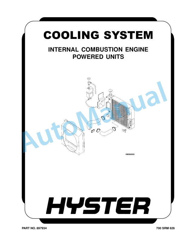
Hyster Cooling System Internal Combustion Engine Powered Units Parts Manual
$30.00
- Type Of Manual: Parts Manual
- Number of Pages: 814
- Size: 27.2MB
- Format: PDF
Description
-
Model List:
- Cooling System Internal Combustion Engine Powered Units
- 1. RM0626-(11-2001)-UK-EN
- 1.1. Cooling System
- 1.2. Safety Precautions Maintenance and Repair
- 1.3. General
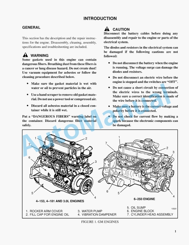
- 1.4. Description
- 1.5. Radiator
- 1.6. Radiator Cap
- 1.7. Thermostat
- 1.8. Water Pump
- 1.9. Fan and Fan Shroud
- 1.10. Cooling System Checks
- 1.11. Radiator
- 1.12. Thermostat
- 1.13. Water Pump
- 1.14. Exhaust Leaks
- 1.15. Fan and Fan Shroud
- 1.16. Radiator Cleaning
- 1.17. Troubleshooting
- 2. RM0656-(09-2005)-UK-EN
- 2.1. Safety Precautions Maintenance and Repair
- 2.2. General
- 2.3. Description
- 2.4. Counterweights
- 2.5. Center Counterweight
- 2.6. Counterweight
- 2.7. Fender Counterweight
- 2.8. Install
- 2.9. Hood and Air Filter Repair
- 2.10. Install
- 2.11. Hydraulic Tank Repair
- 2.12. Repairs, All Units
- 2.13. Small Leaks
- 2.14. Large Leaks
- 2.15. Steam Method
- 2.16. Chemical Solution Method
- 2.17. Other Methods of Preparation for Repair
- 2.18. Install
- 2.19. Fuel Tank Repair
- 2.20. Install
- 2.21. Radiator Repair
- 2.22. Install
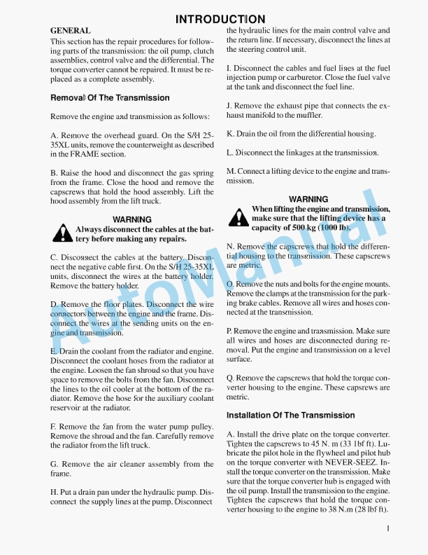
- 2.23. Engine and Transmission Repair
- 2.24. Install
- 2.25. Operator Compartment Repair
- 2.26. General
- 2.27. Install
- 2.28. Window Wipers
- 2.29. Window Washer Motors and Pumps
- 2.30. Heater Control Panel Assembly
- 2.31. Blower and Core Assemblies
- 2.32. Install
- 2.33. Window Replacement
- 2.34. Front and Rear Windows
- 2.35. Lower Door Windows
- 2.36. Upper Door (Sliding) Windows
- 2.37. Top Window
- 2.38. Operator Restraint System
- 2.39. Oil Cooler
- 2.40. Install
- 2.41. Label Replacement
- 2.42. Painting Instructions
- 2.43. Table 1. Counterweights
- 2.44. Table 2. Cab Windows Material Specifications
- 3. RM0657-(07-2007)-UK-EN
- 3.1. Planetary Drive Axle
- 3.2. Safety Precautions Maintenance and Repair
- 3.3. General
- 3.4. Description
- 3.5. Drive Axle Repair
- 3.6. Install
- 3.7. Planetary Gear and Service Brake Repair
- 3.8. Disassemble
- 3.9. Assemble
- 3.10. Axle Hardware Torque
- 3.11. Troubleshooting
- 3.12. Table 1. Approximate Weights of Axle Parts
- 4. RM0658-(09-2014)-UK-EN
- 5. RM0659-(09-2003)-UK-EN
- 5.1. Brake System
- 5.2. Safety Precautions Maintenance and Repair
- 5.3. General
- 5.4. Description and Operation
- 5.5. Parking Brake
- 5.6. Brake Pedal Valves
- 5.7. Pilot Supply Valve Repair
- 5.8. Repairs
- 5.9. Checks and Adjustments
- 5.10. Accumulator Replacement
- 5.11. Oil Cooler
- 5.12. Install
- 5.13. Brake Pedal Components
- 5.14. Manifold
- 5.15. Shuttle Valve
- 5.16. Remove and Disassemble
- 5.17. Clean and Inspect
- 5.18. Assemble and Install
- 5.19. Brake Pedal Valves
- 5.20. Remove and Disassemble
- 5.21. Clean and Inspect
- 5.22. Assemble
- 5.23. Install
- 5.24. Parking Brake Valve Repair
- 5.25. Install
- 5.26. Parking Brake Caliper Repair
- 5.27. Brake System Air Removal
- 5.28. Service Brakes Air Removal
- 5.29. Troubleshooting
- 5.30. Table 1. Hydraulic System Check Ports
- 6. RM0660-(09-2014)-UK-EN
- 7. RM0661-(10-2014)-UK-EN
- 8. RM0662-(05-1997)-UK-EN
- 8.1. PERIODIC MAINTENANCE
- 8.2. MAINTENANCE PROCEDURES
- 8.3. EVERY 8 HOURS OR DAILY
- 8.4. EVERY 250 HOURS OR TWO MONTHS
- 8.5. EVERY 1000 HOURS OR SIX MONTHS
- 8.6. EVERY 2000 HOURS OR YEARLY
- 8.7. GENERAL PROCEDURES
- 8.8. SAFETY PROCEDURES WHEN WORKING NEAR THE MAST
- 8.9. TIRES AND WHEELS
- 9. RM0663-(10-2005)-UK-EN
- 9.1. Diagrams
- 9.2. Safety Precautions Maintenance and Repair
- 10. RM0664-(08-2002)-UK-EN
- 10.1. Capacities and Specifications
- 10.2. Safety Precautions Maintenance and Repair
- 10.3. Lift Truck Weights
- 10.4. Container Attachment Weights
- 10.5. Engine Specifications
- 10.6. Capacities
- 10.7. Hydraulic System
- 10.8. Steering
- 10.9. Electrical System
- 10.10. Mast Speeds
- 10.11. Tire Sizes
- 10.12. Transmission Pressures
- 10.13. Torque Specifications
- 10.14. Container Attachment
- 10.15. Drive Line and Axle
- 10.16. Steering
- 10.17. Transmission
- 10.18. Table 1. Basic Truck as Counterweighted for Standard Pin Fork Op
- 10.19. Table 2. Basic Truck as Counterweighted for Quick Disconnect Hoo
- 11. RM0671-(09-2003)-UK-EN
- 11.1. Steering System
- 11.2. Safety Precautions Maintenance and Repair
- 11.3. General
- 11.4. Description
- 11.5. Steering Wheel and Column Assembly Repair
- 11.6. General
- 11.7. Steering Wheel and Horn
- 11.8. Install
- 11.9. Steering Control Unit Repair
- 11.10. Description
- 11.11. Operation
- 11.12. Load Sensing Steering
- 11.13. Disassemble
- 11.14. Assemble and Install
- 11.15. Steering System Air Removal
- 11.16. Steering Relief Pressure Check
- 11.17. Troubleshooting
- 11.18. Table 1. Hydraulic System Check Ports
- 12. RM0666-(09-2002)-UK-EN
- 12.1. Hydraulic System
- 12.2. Safety Precautions Maintenance and Repair
- 12.3. General
- 12.4. Description and Operation
- 12.5. Main Control Valve
- 12.6. Remote Control Valve
- 12.7. Pilot Supply Valve
- 12.8. Auxiliary Control Valve
- 12.9. Selector Valves
- 12.10. Steering System
- 12.11. Main Control Valve Repair
- 12.12. Description
- 12.13. Lifting
- 12.14. Lowering
- 12.15. Tilt Spool
- 12.16. Priority Valve
- 12.17. Relief Valves
- 12.18. Repairs
- 12.19. Disassemble
- 12.20. Clean and Inspect
- 12.21. Assemble
- 12.22. Install
- 12.23. Checks and Adjustments
- 12.24. Relief Pressures Check
- 12.25. Remote Control Valve Repair
- 12.26. Description
- 12.27. Operation
- 12.28. Repairs
- 12.29. Disassemble
- 12.30. Clean and Inspect
- 12.31. Assemble
- 12.32. Install
- 12.33. Pilot Supply Valve Repair
- 12.34. Description and Operation
- 12.35. Repairs
- 12.36. Checks and Adjustments
- 12.37. Relief Valve, Check and Adjust
- 12.38. Pressure Reduction Valves, Check
- 12.39. Auxiliary Control Valve Repair
- 12.40. Description and Operation
- 12.41. Repairs
- 12.42. Disassemble
- 12.43. Clean and Inspect
- 12.44. Assemble
- 12.45. Install
- 12.46. Check and Adjust
- 12.47. Hydraulic Pump Repair
- 12.48. General
- 12.49. Repairs
- 12.50. Specifications
- 12.51. Troubleshooting
- 12.52. Main Control Valve
- 12.53. Remote Control valve
- 12.54. Pilot Supply Valve
- 12.55. Accumulator Charge Valve and Accumulator
- 12.56. Pressure Reduction Valves
- 12.57. Auxiliary Control Valve
- 12.58. Table 1. Hydraulic System Check Ports
- 13. RM0668-(05-1997)-UK-EN
- 13.1. EMPTY CONTAINER ATTACHMENT
- 13.2. REPAIRS
- 13.3. CHECKS AND ADJUSTMENTS
- 13.4. TROUBLESHOOTING
- 14. RM0669-(05-1997)-UK-EN
- 14.1. ZF TRANSMISSION REPAIR
- 14.2. CHECKS AND ADJUSTMENTS
- 14.3. TROUBLESHOOTING
- 15. RM0046-(11-2014)-UK-EN
- 16. RM0103-(03-2007)-UK-EN
- 16.1. Tilt Cylinders
- 16.2. Safety Precautions Maintenance and Repair
- 16.3. General
- 16.4. Description
- 16.5. Tilt Cylinder Repair
- 16.6. Disassemble
- 16.7. Assemble
- 16.8. Tilt Cylinders With O-Ring or Single-Lip Seals
- 16.9. Tilt Cylinders for XM and XMS Models
- 16.10. Tilt Cylinders for XL, XLS, and XL 3 Models
- 16.11. Tilt Cylinders for H700-800A and Early Model H700-920B
- 16.12. Install
- 16.13. Tilt Cylinders Using Chevron Packing
- 16.14. Tilt Cylinder Leak Check
- 16.15. Tilt Cylinder Stroke and Mast Tilt Angle Adjustment
- 16.16. Torque Specifications
- 16.17. Piston Rod Nut
- 16.18. Retainer
- 16.19. Troubleshooting
- 16.20. Table 1. Movement Rates (Maximum) for Tilt Cylinders
- 17. RM0143-(02-2007)-UK-EN
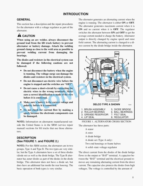
- 17.1. Instrument Panel Indicators and Senders
- 17.2. Safety Precautions Maintenance and Repair
- 17.3. General
- 17.4. Description
- 17.5. Steering Column Gauges, Meters, and Indicators
- 17.6. LED Display Panel
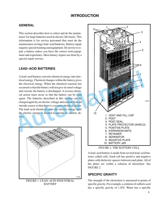
- 17.7. Battery Discharge Indicators
- 17.8. Brush Wear Indicators
- 17.9. Motor Temperature Indicators
- 17.10. LX Series Display Panel
- 17.11. Hourmeter Functions
- 17.12. Battery Indicator Function
- 17.13. Status Code Function
- 17.14. ZX Series Display Panels
- 17.15. Display Panel
- 17.16. Basic Display Panels
- 17.17. Performance Display
- 17.18. Brush Wear Indicators
- 17.19. Adjustments – General
- 17.20. Replacement – General Information
- 17.21. Meter Replacement
- 17.22. Sender Replacement
- 17.23. Fuel Level Sender
- 17.24. Pressure and Temperature Sender
- 17.25. Seat Sensor, Operator Presence System (OPS)
- 17.26. Install
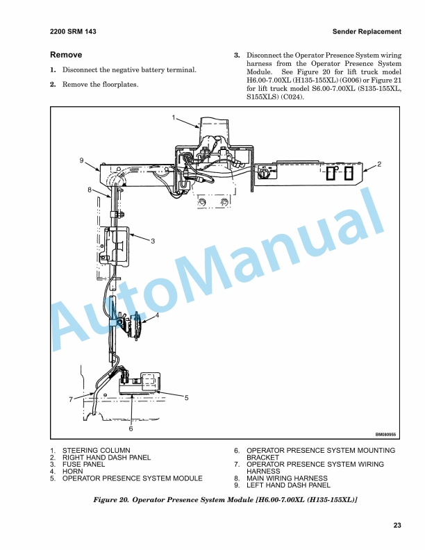
- 17.27. Operator Presence System Module Replacement
- 17.28. Install
- 17.29. ITW Display Panel Replacement
- 17.30. Column Mount Display Panel (EV-100/200ZX Motor Controllers) Repl
- 17.31. Display Panel Assembly, Replace
- 17.32. Indicator LEDs
- 17.33. Battery Indicators
- 17.34. Digital Display (Performance Display Panel Only)
- 17.35. Status Code or Performance Level Switches and Indicator LEDs (Pe
- 17.36. Basic Display Panel, Replace Parts
- 17.37. Performance Display Panel, Replace Parts
- 17.38. Dash Mount Display Panel (EV100/200ZX Motor Controllers) Replace
- 17.39. Remove and Replace
- 17.40. Specifications
- 17.41. Meter Specifications
- 17.42. Sender Specifications
- 17.43. Troubleshooting
- 17.44. Troubleshooting for Operator Presence System
- 17.45. Table 1. Troubleshooting Procedure for Operator Presence Module
- 18. RM0135-(10-2011)-UK-EN
- 18.1. Lift Cylinders
- 18.2. Safety Precautions Maintenance and Repair
- 18.3. Safety Procedures When Working Near Mast
- 18.4. General
- 18.5. Description
- 18.6. Lowering Control Valve
- 18.7. Cylinders (General)
- 18.8. Cylinders (H520-620B, H700-800A)
- 18.9. Retainer, Install
- 18.10. Cylinders (H360-460B)
- 18.11. Cylinders (Two-Speed)
- 18.12. Lift Cylinder Repair
- 18.13. Lift Cylinder Removal Without Removing Mast
- 18.14. Standard Masts With Main Lift Cylinder Fastened to Crossmember o
- 18.15. Standard and Full Free-Lift Masts With Lift Cylinder Fastened to
- 18.16. Masts That Have Two Cylinders, Main Lift Cylinder and Free-Lift
- 18.17. Disassemble
- 18.18. Assemble
- 18.19. Lift Cylinder Installation in Mast
- 18.20. Standard Masts With Main Lift Cylinder Fastened to Crossmember o
- 18.21. Standard and Full Free-Lift Masts With Lift Cylinder Fastened to
- 18.22. Chevron-Style Packing
- 18.23. Chevron-Style Packing Installation on Piston
- 18.24. Chevron-Style Packing Installation in Packing Gland
- 18.25. Lift Cylinders for VISTA Masts
- 18.26. Description
- 18.27. Lowering Control Valve
- 18.28. Disassemble
- 18.29. Assemble
- 18.30. Install
- 18.31. Main Lift Cylinders
- 18.32. Free-Lift Cylinder
- 18.33. Lift System Leak Check
- 18.34. Specifications
- 18.35. Troubleshooting
- 18.36. Table 1. Lift Trucks With Two-Speed Lift Cylinders
- 18.37. Table 2. Cylinder Retainer Torque Specifications and Weight Guid
- 19. RM0231-(01-2016)-UK-EN
- 19.1. General
- 20. RM0990-(05-2006)-UK-EN
- 20.1. Empty Container Handling Attachment
- 20.2. Safety Precautions Maintenance and Repair
- 20.3. General
- 20.4. Description
- 20.5. Operation
- 20.6. General
- 20.7. Selector Valves
- 20.8. Sideshift Circuit
- 20.9. Extend and Retract Circuit
- 20.10. Twist Lock Circuit and Control
- 20.11. Model 572 – Double Horizontally Mounted
- 20.12. Model 573 – Horizontally Mounted
- 20.13. Model 578 – Vertically Mounted
- 20.14. Lifting Hooks
- 20.15. Model 575
- 20.16. Indicator Lights and LEDs
- 20.17. Lift Interrupt and Override
- 20.18. Overlowering Interrupt and Override
- 20.19. Second Container Detection Sensor (Model 572 Only)
- 20.20. Carriage and Attachment Repair
- 20.21. Attachment Without Carriage Repair
- 20.22. Sideshift Cylinders Repair
- 20.23. Disassemble
- 20.24. Assemble
- 20.25. Extension Cylinders Repair
- 20.26. Disassemble
- 20.27. Clean and Inspect
- 20.28. Assemble
- 20.29. Install
- 20.30. Floating End Beams Repair
- 20.31. Install
- 20.32. Hose Replacement In End Beams
- 20.33. Twist Locks Repair for Model 572 and 573
- 20.34. Model 573
- 20.35. Model 572
- 20.36. Disassemble
- 20.37. Clean and Inspect
- 20.38. Assemble
- 20.39. Hook Replacement for Model 575
- 20.40. Inspect
- 20.41. Install
- 20.42. Twist Locks Repair for Model 578
- 20.43. Disassemble
- 20.44. Clean and Inspect
- 20.45. Assemble
- 20.46. Extension Beams Repair
- 20.47. LH and RH Extension Beam, Remove
- 20.48. Slave Beam, Remove
- 20.49. Clean and Inspect
- 20.50. Assemble
- 20.51. Bleed the System
- 20.52. Valve Assembly
- 20.53. Slide Pad Replacement
- 20.54. Adjustments
- 20.55. Twist Lock Angle Adjustment
- 20.56. Model 578 Only
- 20.57. LOCKED/NOT LOCKED Sensors Adjustment
- 20.58. Model 573
- 20.59. Model 578
- 20.60. Seated Sensor Adjustment
- 20.61. Model 572 and 573




%20Parts%20Manual&url=https://pdfrepairmanual.com/docs/hyster-b108-e30-60bs-parts-manual/&media=https://pdfrepairmanual.com/wp-content/uploads/2026/01/hyster-b108-e30-60bs-parts-manual-1.jpg)


%20Parts%20Manual&url=https://pdfrepairmanual.com/docs/hyster-b177-h2-00-3-00xl-parts-manual/&media=https://pdfrepairmanual.com/wp-content/uploads/2026/01/hyster-b177-h200-300xl-parts-manual-1.jpg)


%20Parts%20Manual&url=https://pdfrepairmanual.com/docs/hyster-b60zac2-e230-parts-manual/&media=https://pdfrepairmanual.com/wp-content/uploads/2026/01/hyster-b60zac2-e230-parts-manual-1.jpg)

,%20B60ZHD2%20(C262)%20Parts%20Manual&url=https://pdfrepairmanual.com/docs/hyster-b80zhd2-c257-b60zhd2-c262-parts-manual/&media=https://pdfrepairmanual.com/wp-content/uploads/2026/01/hyster-b80zhd2-c257-b60zhd2-c262-parts-manual-1.jpg)

There are no reviews yet.