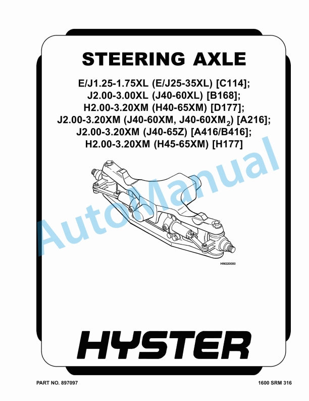
Hyster E-J1.25-1.75XL to H2.00-3.20XM Steering Axle Maintenance And Repair
$30.00
- Type Of Manual: Maintenance And Repair
- Number of Pages: 2037
- Size: 52.4MB
- Format: PDF
Description
-
Model List:
- E-J1.25-1.75XL, J2.00-3.00XL, H2.00-3.20XM, J2.00-3.20XM, J2.00-3.20XM, H2.00-3.20XM
- 1. RM0316-(08-2006)-US-EN
- 1.1. Steering Axle
- 1.2. Safety Precautions Maintenance and Repair
- 1.3. General
- 1.4. Description
- 1.5. Steering Axle Assembly Repair
- 1.6. Install
- 1.7. Wheels and Hubs Repair
- 1.8. Remove and Disassemble
- 1.9. Assemble and Install
- 1.10. Spindles, Bearings, and Tie Rods Repair
- 1.11. Install
- 1.12. Steering Cylinder Repair
- 1.13. Remove and Disassemble
- 1.14. Clean and Inspect
- 1.15. Assemble and Install
- 1.16. Torque Specifications
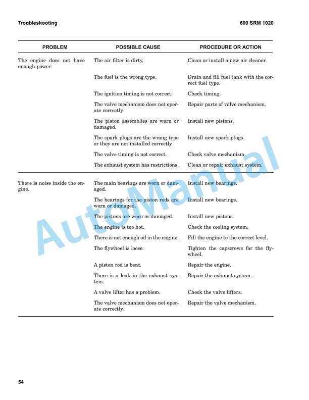
- 1.17. Troubleshooting
- 2. RM0496-(01-2011)-US-EN
- 2.1. Mazda Engine
- 2.2. Safety Precautions Maintenance and Repair
- 2.3. General
- 2.4. Description
- 2.5. Engine Removal and Installation
- 2.6. Cylinder Head, Camshaft, and Valve Mechanism Repair
- 2.7. Inspect and Repair
- 2.8. Cylinder Head
- 2.9. Rocker Shaft Assembly
- 2.10. Camshaft
- 2.11. Valve Guides
- 2.12. Valve Seats
- 2.13. Valve Springs
- 2.14. Install
- 2.15. Crankshaft and Main Bearings Repair
- 2.16. Inspect and Repair
- 2.17. Crankshaft
- 2.18. Main Bearings
- 2.19. Install
- 2.20. Pistons and Connecting Rods Repair
- 2.21. Remove and Disassemble
- 2.22. Inspect and Repair
- 2.23. Pistons
- 2.24. Piston Rings
- 2.25. Connecting Rods and Bearings
- 2.26. Assemble and Install
- 2.27. Cylinder Block Repair
- 2.28. Oil Pump Repair
- 2.29. Disassemble
- 2.30. Inspect
- 2.31. Assemble
- 2.32. Install
- 2.33. Cooling System Repair
- 2.34. Thermostat
- 2.35. Replace
- 2.36. Fan Assembly
- 2.37. Remove and Disassemble
- 2.38. Assemble and Install
- 2.39. Water Pump
- 2.40. Remove and Disassemble
- 2.41. Assemble and Install
- 2.42. Distributor Repair
- 2.43. Install
- 2.44. Flywheel and Ring Gear Repair S/H2.00-3.20XM (S/H40-65XM)
- 2.45. Ring Gear, Replace
- 2.46. Install
- 2.47. Flywheel Repair H1.50-175XM, H2.00XMS (S/H25-35XM, S/H40XMS)
- 2.48. Install
- 2.49. Valve Adjustment
- 2.50. Compression Pressure Check
- 2.51. Engine Timing Adjustment
- 2.52. Throttle Linkage Adjustment
- 2.53. Gasoline Engines
- 2.54. LPG Engines (IMPCO)
- 2.55. LPG Engines (AISAN)
- 2.56. Engine Specifications
- 2.57. Engine Data
- 2.58. Thermostat
- 2.59. Cylinder Head
- 2.60. Valve Mechanism
- 2.61. Camshaft
- 2.62. Crankshaft
- 2.63. Connecting Rods
- 2.64. Cylinder Block
- 2.65. Pistons
- 2.66. Oil Pump
- 2.67. Torque Specifications
- 2.68. Troubleshooting
- 3. RM0499-(10-2004)-US-EN
- 3.1. Drive Axle
- 3.2. Safety Precautions Maintenance and Repair
- 3.3. General
- 3.4. Description
- 3.5. Drive Axle Repair
- 3.6. Remove and Disassemble
- 3.7. Clean and Inspect
- 3.8. Assemble and Install
- 3.9. Torque Specifications
- 3.10. H2.00-3.20XM (H40-65XM)
- 3.11. S2.00-3.20XM (S40-65XM)
- 3.12. Troubleshooting
- 4. RM0500-(08-2003)-US-EN
- 4.1. Single-Speed Powershift Transmission
- 4.2. Safety Precautions Maintenance and Repair
- 4.3. General
- 4.4. Description and Operation
- 4.5. General
- 4.6. Torque Converter
- 4.7. Description
- 4.8. Operation
- 4.9. Clutch Assemblies
- 4.10. Description
- 4.11. Operation
- 4.12. Hydraulic System
- 4.13. General
- 4.14. Control Valve
- 4.15. General
- 4.16. Clutch Pressure Regulator
- 4.17. Inching Spool Assembly
- 4.18. Direction Spool
- 4.19. Modulator Circuit
- 4.20. Torque Converter Regulator
- 4.21. MONOTROL Pedal
- 4.22. MONOTROL Pedal Start Circuit
- 4.23. Direction Control Lever
- 4.24. Differential
- 4.25. Oil Flow Diagrams
- 4.26. Neutral
- 4.27. Modulator Operation
- 4.28. Forward
- 4.29. Forward-Inching
- 5. RM0501-(03-2004)-US-EN
- 5.1. Single-Speed Powershift Transmission
- 5.2. Safety Precautions Maintenance and Repair
- 5.3. General
- 5.4. Transmission Removal
- 5.5. Torque Converter and Housing Repair
- 5.6. Install
- 5.7. Transmission Pump Repair
- 5.8. Install
- 5.9. Front Cover and Pump Drive Repair
- 5.10. Remove and Disassemble
- 5.11. Assemble and Install
- 5.12. Clutch Assemblies Repair
- 5.13. Remove and Disassemble
- 5.14. Inspect
- 5.15. Assemble
- 5.16. Install
- 5.17. Differential Repair
- 5.18. Remove and Disassemble
- 5.19. Inspect
- 5.20. Assemble and Install
- 5.21. Control Valve Repair
- 5.22. Remove and Disassemble
- 5.23. Inspect
- 5.24. Assemble and Install
- 5.25. MONOTROL Pedal Repair
- 5.26. Remove and Disassemble
- 5.27. Assemble and Install
- 5.28. Direction Control Lever Repair
- 5.29. Remove and Disassemble
- 5.30. Assemble and Install
- 5.31. Stall Test
- 5.32. Inching/Brake Pedal Adjustment
- 5.33. Neutral Start Switch, MONOTROL Pedal Adjustment H2.00-3.20XM (H4
- 5.34. Neutral Start Switch, MONOTROL Pedal Adjustment S2.00-3.20XM (S4
- 5.35. Neutral Start Switch Test, MONOTROL Pedal
- 5.36. Oil Pressure Checks
- 5.37. Relief Valve for Transmission Pump Check, TEST PORT 1
- 5.38. Clutch Pressure Check, TEST PORTS 2 and 3
- 5.39. Torque Converter Regulator Check, TEST PORT 4
- 5.40. Lubrication Circuit Oil Pressure Check, TEST PORT 5
- 5.41. Modulator Pressure Check, TEST PORT 6
- 5.42. Troubleshooting
- 5.43. Troubleshooting – Pressure Tests
- 5.44. Table 1. Adjustment of Shims for Pinion Assembly
- 5.45. Table 2. Ring and Pinion Tooth Contact Adjustment
- 5.46. Table 3. Stall Speeds
- 5.47. Table 4. Transmission Oil Pressures Test Ports
- 6. RM0505-(06-2004)-US-EN
- 6.1. Safety Precautions Maintenance and Repair
- 6.2. General
- 6.3. Description
- 6.4. Operator Module Repair
- 6.5. Install
- 6.6. Hood and Side Covers Repair
- 6.7. Install
- 6.8. Overhead Guard Repair
- 6.9. Remove and Install
- 6.10. LED Backup and Brake Lights, Replace
- 6.11. Install
- 6.12. Counterweight Repair
- 6.13. Install
- 6.14. Exhaust System Repair
- 6.15. Muffler, Replace
- 6.16. Radiator and Cooling System Repair
- 6.17. Install
- 6.18. Operator Restraint System Repair
- 6.19. Engine Repair
- 6.20. Remove Engine Only
- 6.21. Remove Engine and Transmission
- 6.22. Install Engine Only
- 6.23. Install Engine and Transmission
- 6.24. Fuel and Hydraulic Tanks Repair
- 6.25. Inspect
- 6.26. Small Leaks, Repair
- 6.27. Large Leaks, Repair
- 6.28. Steam Method of Cleaning
- 6.29. Chemical Solution Method of Cleaning
- 6.30. Additional Preparations for Repair
- 6.31. Safety Labels
- 6.32. Table 1. Weight of Counterweights
- 7. RM0506-(05-2005)-US-EN
- 7.1. Brake System
- 7.2. Safety Precautions Maintenance and Repair
- 7.3. General
- 7.4. Description and Operation
- 7.5. Service Brakes
- 7.6. Master Cylinder
- 7.7. Parking Brake
- 7.8. Service Brakes Repair
- 7.9. Remove and Disassemble
- 7.10. Inspect
- 7.11. Assemble and Install
- 7.12. Parking Brake Repair
- 7.13. Remove and Disassemble
- 7.14. Assemble and Install
- 7.15. Master Cylinder Repair
- 7.16. Clean and Inspect
- 7.17. Install
- 7.18. Service Brakes Adjustment
- 7.19. Brake System Air Removal
- 7.20. Parking Brake Not Applied Switch Test
- 7.21. Parking Brake Switch Test (MONOTROL Pedal Only)
- 7.22. Inching/Brake Pedal Adjustment
- 7.23. Neutral Start Switch Adjustment, MONOTROL Pedal H2.00-3.20XM (H4
- 7.24. Neutral Start Switch Adjustment, MONOTROL Pedal S2.00-3.20XM (S4
- 7.25. Neutral Start Switch Test (MONOTROL Pedal)
- 7.26. Torque Specifications
- 7.27. H2.00-3.20XM (H40-65XM)
- 7.28. S2.00-3.20XM (S40-65XM)
- 7.29. Troubleshooting
- 8. RM0513-(06-2004)-US-EN
- 8.1. Hydraulic System
- 8.2. Safety Precautions Maintenance and Repair
- 8.3. General
- 8.4. Description
- 8.5. Hydraulic System
- 8.6. Gear Pump Assembly
- 8.7. Flow Control Valve
- 8.8. Relief Valve
- 8.9. Operation
- 8.10. Hydraulic System
- 8.11. Gear Pump
- 8.12. Flow Control Valve
- 8.13. Relief Valve
- 8.14. Gear Pump Assembly Repair
- 8.15. Remove and Disassemble
- 8.16. Assemble and Install
- 8.17. Steering Relief Pressure Check and Adjustment
- 8.18. Gear Pump Flow Check
- 8.19. Troubleshooting
- 9. RM0514-(01-2004)-US-EN
- 9.1. Instrument Cluster
- 9.2. Safety Precautions Maintenance and Repair
- 9.3. General
- 9.4. Description
- 9.5. Display Panels on Steering Column, Internal Combustion
- 9.6. Display Panels on Steering Column, Electric Lift Trucks
- 9.7. Standard Display Panel
- 9.8. Enhanced Display Panel
- 9.9. Curtis 1215 Display Panel
- 9.10. Description and Features
- 9.11. Operation
- 9.12. Cluster-Type Display Panel (Internal Combustion) Replacement
- 9.13. Remove and Disassemble
- 9.14. Assemble and Install
- 9.15. Cluster Display Panel (Electric Lift Truck) Replacement
- 9.16. Display Panel Assembly, Replace
- 9.17. LED Indicators
- 9.18. Battery Indicators
- 9.19. Digital Display (Enhanced Display Panel Only)
- 9.20. Status Code or Performance Level Switches and LED indicators (En
- 9.21. Standard Display Panel Parts, Replace
- 9.22. Enhanced Display Panel Parts, Replace
- 9.23. Curtis 1215 Display Panel Replacement
- 9.24. Install
- 9.25. Table 1. Instrument Cluster, Internal Combustion
- 10. RM0521-(03-2006)-US-EN
- 10.1. Safety Precautions Maintenance and Repair
- 10.2. General
- 10.3. Description and Operation
- 10.4. Carriages
- 10.5. Mast Mounts
- 10.6. Two-Stage Mast, Limited Free-Lift (LFL)
- 10.7. Description and Operation
- 10.8. Two-Stage Mast, Full Free-Lift (FFL)
- 10.9. Description and Operation
- 10.10. Three-Stage Mast, Full Free-Lift (FFL)
- 10.11. Description and Operation
- 10.12. Four-Stage Mast
- 10.13. Description and Operation
- 10.14. Cylinder Cushion During Lifting Sequence
- 10.15. Cylinder Cushion During Lowering Sequence
- 11. RM0522-(07-2010)-US-EN
- 11.1. Mast Repairs
- 11.2. Safety Precautions Maintenance and Repair
- 11.3. General
- 11.4. Safety Procedures When Working Near Mast
- 11.5. Fork Repair
- 11.6. Install
- 11.7. Carriages Repair
- 11.8. Standard Carriage, Remove
- 11.9. Hang-On Sideshift Carriage, Remove
- 11.10. Standard Carriage and Hang-On Sideshift Carriage, Repair
- 11.11. Standard Carriage, Install
- 11.12. Hang-On Sideshift Carriage, Install
- 11.13. Integral Sideshift Carriage
- 11.14. Clean and Inspect
- 11.15. Install
- 11.16. Mast Repair
- 11.17. Two-Stage LFL and Two-Stage FFL Masts, Disassemble
- 11.18. Three-Stage FFL Mast
- 11.19. Disassemble
- 11.20. Mast and Chains, Clean and Inspect
- 11.21. Two-Stage LFL and Two-Stage FFL Mast, Assemble
- 11.22. Three-Stage FFL Mast, Assemble
- 11.23. Install
- 11.24. Lift Cylinders Repair
- 11.25. Main Lift Cylinders, Remove
- 11.26. Free-Lift Cylinder, Remove
- 11.27. Cylinders, Disassemble
- 11.28. Two-Stage Full Free-Lift Mast, Right-Hand Main Lift Cylinder
- 11.29. Two-Stage Full Free-Lift Mast, Left-Hand Main Lift Cylinder
- 11.30. Two-Stage Limited Free-Lift Mast and Three-Stage Full Free-Lift
- 11.31. Two-Stage Limited Free-Lift Mast and Three-Stage Full Free-Lift
- 11.32. Two-Stage Full Free-Lift Mast and Three-Stage Full Free-Lift Mas
- 11.33. Clean and Inspect
- 11.34. Cylinders, Assemble
- 11.35. Two-Stage Full Free-Lift Mast, Right-Hand Main Lift Cylinder
- 11.36. Two-Stage Full Free-Lift Mast, Left-Hand Main Lift Cylinder
- 11.37. Two-Stage Limited Free-Lift Mast and Three-Stage Full Free-Lift
- 11.38. Two-Stage Limited Free-Lift Mast and Three-Stage Full Free-Lift
- 11.39. Two-Stage Full Free-Lift Mast and Three-Stage Full Free-Lift Mas
- 11.40. Main Lift Cylinders, Install
- 11.41. Free-Lift Cylinder, Install
- 11.42. Header Hose Arrangements
- 11.43. Two-Stage LFL Mast, New Hose Install
- 11.44. Two-Stage LFL Mast, Adjust Hoses After Installation
- 11.45. Two-Stage FFL Mast, New Hose Install
- 11.46. Two-Stage FFL Mast, Adjust Hoses After Installation
- 11.47. Three-Stage FFL Mast, New Hose Install
- 11.48. Three-Stage FFL Mast, Adjust Hoses After Installation
- 11.49. Header Hose Arrangement
- 11.50. Two-Stage LFL Mast, New Hose Install
- 11.51. Two-Stage LFL Mast, Adjust Hoses After Installation
- 11.52. Two-Stage FFL Mast, New Hose Install
- 11.53. Two-Stage FFL Mast, Adjust Hoses After Installation
- 11.54. Three-Stage FFL Mast, New Hose Install
- 11.55. Three-Stage FFL Mast, Adjust Hoses After Install
- 11.56. Lift and Tilt System Leak Check
- 11.57. Lift Cylinders Leak Check
- 11.58. Tilt Cylinders Leak Check
- 11.59. Tilt Cylinders Adjustment
- 11.60. Lift Chains Adjustment
- 11.61. Mast Adjustment
- 11.62. Carriage Adjustment
- 11.63. Troubleshooting
- 11.64. Table 1. Hook-Type Carriage Chain Adjustment
- 11.65. Table 2. Pin-Type Carriage Chain Adjustment
- 12. RM0524-(02-2001)-US-EN
- 12.1. Electrical System
- 12.2. Safety Precautions Maintenance and Repair
- 12.3. General
- 12.4. Description
- 12.5. Starting System
- 12.6. Ignition System
- 12.7. Charging System
- 12.8. Starter Repair


%20Service%20Manual&url=https://pdfrepairmanual.com/docs/hyster-b160-j25-35bs-service-manual/&media=https://pdfrepairmanual.com/wp-content/uploads/2026/01/hyster-b160-j25-35bs-service-manual-1.jpg)

%20Service%20Manual&url=https://pdfrepairmanual.com/docs/hyster-c007-h150-275hp150-200b-service-manual/&media=https://pdfrepairmanual.com/wp-content/uploads/2026/01/hyster-c007-h150-275hp150-200b-service-manual-1.jpg)
%20Service%20Manual&url=https://pdfrepairmanual.com/docs/hyster-b447-s1-0c-s1-2c-s1-5c-service-manual/&media=https://pdfrepairmanual.com/wp-content/uploads/2026/01/hyster-b447-s10c-s12c-s15c-service-manual-1.jpg)

%20Service%20Manual&url=https://pdfrepairmanual.com/docs/hyster-c001-h1-25-1-75xl-service-manual/&media=https://pdfrepairmanual.com/wp-content/uploads/2026/01/hyster-c001-h125-175xl-service-manual-1.jpg)

%20Service%20Manual&url=https://pdfrepairmanual.com/docs/hyster-a406-r1-4-r1-6-service-manual/&media=https://pdfrepairmanual.com/wp-content/uploads/2026/01/hyster-a406-r14-r16-service-manual-1.jpg)
%20Maintenance%20Schedule&url=https://pdfrepairmanual.com/docs/hyster-c098-e3-50-5-50xl-e4-50xls-maintenance-schedule/&media=https://pdfrepairmanual.com/wp-content/uploads/2026/01/hyster-c098-e350-550xl-e450xls-maintenance-schedule-1.jpg)

There are no reviews yet.