Hyster Battery Indicators Maintenance And Repair
$30.00
- Type Of Manual: Maintenance And Repair
- Number of Pages: 366
- Size: 7.3MB
- Format: PDF
Description
- 1. RM0138-(08-2016)-US-EN
- 1.1. General
- 1.1.1. Indicators With Meter Movements
- 1.1.2. Battery Indicators With LCD or LED Displays
- 1.2. Battery Indicators Without Lift Interrupt Adjustment (Early Models)
- 1.3. Battery Indicators With Lift Interrupt Adjustment (Early Models)
- 1.3.1. Reset Potentiometer
- 1.3.2. Specific Gravity Alarm
- 1.4. Battery Indicators Without Lift Interrupt Check (Later Models)
- 1.5. Battery Indicators With Lift Interrupt Adjustment (Later Models)
- 1.5.1. Reset Potentiometer
- 1.5.2. Discharge Potentiometer
- 1.6. LED Display With Lift Interrupt
- 1.7. Curtis 933-1 Meter Check and Adjustment
- 1.7.1. Reset Check
- 1.7.2. Discharge Check
- 1.7.3. Lockout Check
- 1.7.4. LEDs Do Not Illuminate
- 1.7.5. Hourmeter Check
- 1.7.6. Hourglass Icon
- 1.8. SEVCON POWERGAUGE Adjustment
- 1.9. Curtis Dash Display Assembly
- 1.9.1. Description/Features
- 1.9.2. Operation
- 1.9.3. Testing
- 1.9.4. Install
- 1.9.5. Adjust (Setup, Early Models)
- 1.9.6. Adjust (Setup, Later Model)
- 1.10. Battery Indicators Replacement
- 1.11. Battery Indicator Controller Replacement
- 1.12. Display Panel Components Replacement
- 1.13. SEM Display Panel Replacement
- 1.13.1. Remove and Replace
- 2. RM0231-(08-2016)-US-EN
- 2.1. General
- 2.1.1. Threaded Fasteners
- 2.1.2. Nomenclature, Threads
- 2.1.3. Strength Identification
- 2.1.4. Cotter (Split) Pins
- 2.1.5. Fastener Torque Tables
- 2.1.6. Conversion Table
- 3. RM0919-(09-2016)-US-EN
- 3.1. General
- 3.1.1. How to Move a Disabled Truck
- 3.1.2. How to Raise the Lift Truck
- 3.1.3. How to Put a Lift Truck on Blocks
- 3.1.4. Welding Repairs
- 3.2. Maintenance Schedule
- 3.2.1. Checks and Inspection Procedures
- 3.2.2. Casters
- 3.3. Lubrication Instructions
- 3.3.1. Every 8 Hours or Daily
- 3.3.2. Every 50 Hours or 1 Month
- 3.3.3. Every 350 Hours or 2 Months
- 3.3.4. Every 2000 Hours or 1 Year
- 3.4. Recommended Schedule of Maintenance
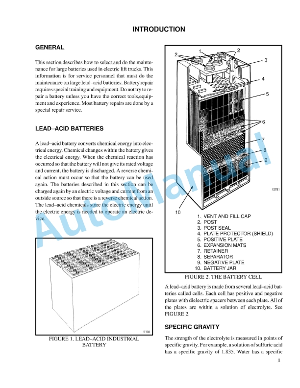
- 3.5. Battery Maintenance
- 3.5.1. How to Charge the Battery
- 3.5.2. How to Change the Battery
- 4. RM0920-(08-2016)-US-EN
- 4.1. General Notes
- 5. RM0929-(08-2016)-US-EN
- 5.1. General
- 5.2. Electrical System Checks
- 5.2.1. Safety Precautions
- 5.3. Repairs
- 5.3.1. Controller, Replace
- 5.3.2. Contactor Coil, Check
- 5.3.3. Contactor, Replace
- 5.3.4. Contactor Tips, Replace
- 5.4. Brake Switch – W60Z, W65Z, W80Z, B60Z (Aug. 2003) and B80Z (Aug. 2003)
- 5.4.1. Remove and Install
- 5.5. Brake and Interlock Switches – B60Z (Aug. 2003) and B80Z (Aug. 2003)
- 5.5.1. Disassemble
- 5.5.2. Assemble
- 5.6. Height Limit
- 5.7. Control Handle
- 5.7.1. Disassemble
- 5.7.2. Control Handle Card (Old Style)
- 5.7.3. Control Handle Card (New Style)
- 5.7.4. Assemble
- 5.8. Remote Control Box Switches (B60Z and B80Z)
- 5.8.1. Install
- 5.9. Motor Maintenance – General
- 5.10. Brush and Commutator Inspection
- 5.10.1. Commutator Problems
- 5.11. Brush Replacement
- 5.12. Drive Motor
- 5.12.1. Disassemble
- 5.12.2. Assemble
- 5.12.3. Install
- 5.13. Lift Pump Motor
- 5.13.1. Install
- 5.14. Commutator Repairs
- 5.15. Testing the Drive Motor
- 5.15.1. Damaged Field and Armature
- 5.15.2. Short Circuit in an Armature Winding
- 5.15.3. Short Circuit in the Armature
- 5.15.4. Open Circuit in a Field Coil
- 5.15.5. Short Circuit in a Field Coil
- 5.15.6. Short Circuit Between Field and Motor Case
- 5.15.7. Brush Holder
- 5.16. Troubleshooting
- 6. RM0918-(08-2016)-US-EN
- 6.1. Hydraulic System
- 6.2. Hydraulic Oils
- 6.3. Gear Oils
- 6.4. Truck Weights
- 6.4.1. Weight (Basic Truck Without Battery)
- 6.4.2. Drive Tire
- 6.5. Torque Specifications
- 6.5.1. Caster Assembly
- 6.5.2. Master Drive Unit
- 6.5.3. Steering
- 6.5.4. Electrical
- 6.5.5. Lift Mechanism
- 6.6. Battery Specifications and Adjustments
- 6.6.1. B60Z and W60Z 24 Volt
- 6.6.2. W65Z 12 Volt
- 6.6.3. B80Z 24 Volt
- 6.6.4. W80Z 24 Volt
- 7. RM0928-(08-2016)-US-EN
- 7.1. General
- 7.1.1. Safety Precautions
- 7.2. Description
- 7.2.1. Curtis PMC 1297 Transistor Motor Controller
- 7.2.2. Principles of Operation
- 7.2.3. Install
- 7.2.4. Programming Controller
- 7.3. Programmer Handset
- 7.3.1. Description/Features
- 7.3.2. Scroll Display Keys
- 7.3.3. Change Value Keys
- 7.3.4. More Info Key
- 7.4. Operation
- 7.4.1. Connecting Handset to Traction Motor Controller
- 7.4.2. Disconnecting Handset From Traction Motor Controller
- 7.4.3. Programmer Self-Test
- 7.4.4. Menu Selections
- 7.5. Programming Traction Motor Controller – 1307 Handset
- 7.6. Programmer Handset
- 7.6.1. Description/Features
- 7.6.2. Operation
- 7.6.3. Main Menu Selections
- 7.7. Programming the Traction Motor Controller – 1311 Handset
- 7.8. Parameters
- 7.8.1. Adjusting Parameters
- 7.9. Battery Discharge Indicator (BDI)/Hourmeter
- 7.10. LED Fault Codes
- 7.11. Control Card Functional Test
- 8. RM0960-(08-2016)-US-EN
- 8.1. General
- 8.2. Frame Separation and Assembly
- 8.2.1. Frame Separation
- 8.2.2. Frame Assembly
- 8.3. Painting Instructions
- 8.4. Label Replacement
- 9. RM0962-(08-2016)-US-EN
- 9.1. General
- 9.2. Special Precautions
- 9.3. Control Handle Head
- 9.4. Control Handle (W60/65/80Z, W30/40ZA, W20/30ZR, and W25/30/40ZC)
- 9.4.1. Install
- 9.5. Control Handle (B60/80Z)
- 9.5.1. Remove (Handle)
- 9.5.2. Steer Bearings and Support
- 9.5.3. Install (Handle)
- 9.6. Gas Spring
- 9.6.1. Discharging the Gas Spring
- 9.6.2. Remove (W60/65/80Z, W30/40ZA, W20/30ZR, and W25/30/40ZC)
- 9.6.3. Remove (B60/80Z)
- 9.6.4. Install (W60/65/80Z, W30/40ZA, W20/30ZR, and W25/30/40ZC)
- 9.6.5. Install (B60/80Z)
- 9.7. Steering and Dash Assembly (Complete)
- 9.7.1. Install
- 9.8. Troubleshooting
- 10. RM0963-(08-2016)-US-EN
- 10.1. General
- 10.2. Description
- 10.3. Special Precautions
- 10.4. Brake Check
- 10.4.1. Hold On Grade Test
- 10.5. Brake Coil Check
- 10.6. Brake Assembly Repair
- 10.6.1. B60Z and W60Z (Up to10/2001)
- 10.6.2. B60Z and W60Z (10/2001 and Up), B80Z, T5Z, T7Z, C60Z, C80Z, W65Z, W80Z, W30/40ZA, W20/30ZR, and W25/30/40ZC
- 10.7. Brake Assembly Adjustment
- 10.7.1. Air Gap, Adjust
- 10.7.2. Torque Nut, Adjust
- 10.8. Troubleshooting
- 11. RM0964-(08-2016)-US-EN
- 11.1. General
- 11.2. Description of Operation
- 11.2.1. Lifting a Load
- 11.2.2. Lowering a Load
- 11.2.3. Hydraulic Lines
- 11.2.4. Hydraulic Oil
- 11.2.5. Sound Level
- 11.3. Special Precautions
- 11.4. Hydraulic Reservoir
- 11.4.1. Description
- 11.5. Drive Unit Compartment Covers
- 11.5.1. C60Z, C80Z, C60ZAC, and C80ZAC
- 11.5.2. B60Z, B80Z, B60ZAC, B80ZAC, W60Z, W65Z, and W80Z
- 11.6. Lift Pump and Motor
- 11.6.1. General
- 11.6.2. Disassemble
- 11.6.3. Assemble
- 11.6.4. Install
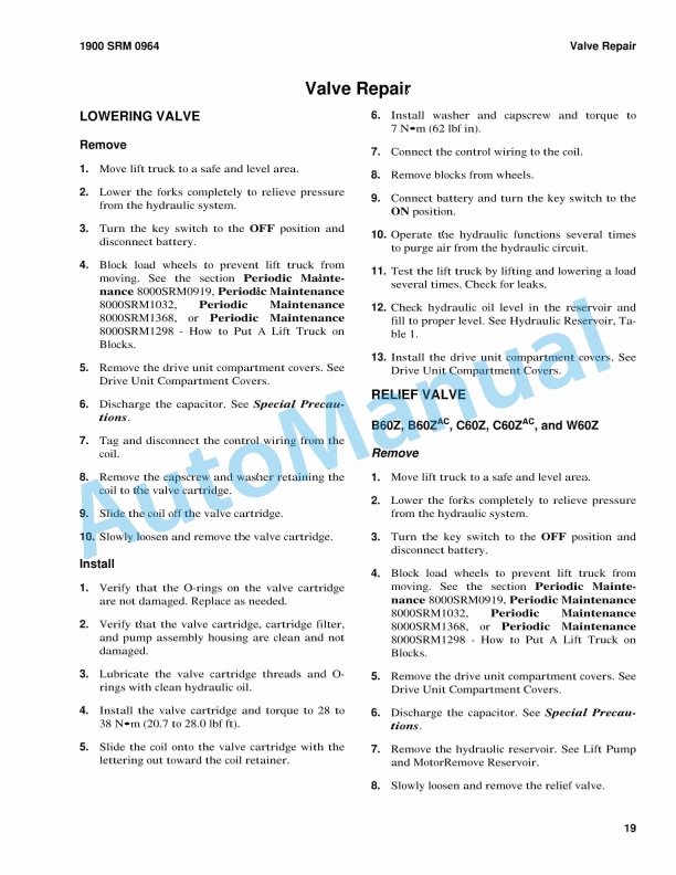
- 11.7. Valve Repair
- 11.7.1. Lowering Valve
- 11.7.2. Relief Valve
- 11.7.3. Check Valve
- 11.8. Lift Cylinder
- 11.8.1. Disassemble
- 11.8.2. Assemble
- 11.8.3. Install
- 11.9. Relief Valve Adjustment
- 11.9.1. Relief Valve Pressure Check
- 11.9.2. Adjust Relief Valve Pressure
- 11.10. Troubleshooting
- 11.10.1. Lift Assemblies
- 11.10.2. Lift Cylinders
- 11.10.3. Lift Pump and Motor Assembly
- 12. RM0965-(08-2016)-US-EN
- 12.1. General
- 12.2. Description of Operation
- 12.3. Load Wheel
- 12.3.1. Install
- 12.4. Caster Wheels
- 12.4.1. Caster Shim Adjustment
- 12.4.2. Caster Replacement
- 12.4.3. Disassemble
- 12.4.4. Assemble
- 12.4.5. Caster Lubrication
- 12.5. Rear Link and Load Wheel Assembly
- 12.5.1. Install
- 12.6. Pull Rod
- 12.6.1. End Replacement
- 12.6.2. Install
- 12.6.3. Rear Fork Adjustment
- 12.7. Rocker Arm
- 12.7.1. Install
- 12.8. Upper Link
- 12.8.1. Install
- 12.9. Troubleshooting
- 13. RM2005-(08-2016)-US-EN
- 13.1. General
- 13.1.1. Accessing the Drive Unit Compartment
- 13.2. Special Precautions
- 13.2.1. Discharging the Capacitors
- 13.3. Description
- 13.4. AC Motor Repair
- 13.4.1. Install
- 13.5. Troubleshooting
- 14. RM2006-(08-2016)-US-EN
- 14.1. Safety Precautions
- 14.2. General
- 14.2.1. Check Oil Level
- 14.3. Drive Tire
- 14.3.1. Install
- 14.4. Master Drive Unit
- 14.4.1. Disassemble
- 14.5. Troubleshooting


%20Service%20Manual&url=https://pdfrepairmanual.com/docs/hyster-c108-e2-00-3-00xl-service-manual/&media=https://pdfrepairmanual.com/wp-content/uploads/2026/01/hyster-c108-e200-300xl-service-manual-1.jpg)
%20Service%20Manual&url=https://pdfrepairmanual.com/docs/hyster-b160-j25-35bs-service-manual/&media=https://pdfrepairmanual.com/wp-content/uploads/2026/01/hyster-b160-j25-35bs-service-manual-1.jpg)
%20Service%20Manual&url=https://pdfrepairmanual.com/docs/hyster-b210-n30ah-service-manual/&media=https://pdfrepairmanual.com/wp-content/uploads/2026/01/hyster-b210-n30ah-service-manual-1.jpg)
%20Service%20Manual&url=https://pdfrepairmanual.com/docs/hyster-c002-s30-50c-service-manual/&media=https://pdfrepairmanual.com/wp-content/uploads/2026/01/hyster-c002-s30-50c-service-manual-1.jpg)
%20Service%20Manual&url=https://pdfrepairmanual.com/docs/hyster-c005-h60-90c-service-manual/&media=https://pdfrepairmanual.com/wp-content/uploads/2026/01/hyster-c005-h60-90c-service-manual-1.jpg)
%20Service%20Manual&url=https://pdfrepairmanual.com/docs/hyster-c098-e3-50-5-50xl-service-manual/&media=https://pdfrepairmanual.com/wp-content/uploads/2026/01/hyster-c098-e350-550xl-service-manual-1.jpg)

%20Service%20Manual&url=https://pdfrepairmanual.com/docs/hyster-b174-r30es-service-manual/&media=https://pdfrepairmanual.com/wp-content/uploads/2026/01/hyster-b174-r30es-service-manual-1.jpg)
%20Service%20Manual&url=https://pdfrepairmanual.com/docs/hyster-b460-k1-0m-k1-0h-k1-0h-wp-service-manual/&media=https://pdfrepairmanual.com/wp-content/uploads/2026/01/hyster-b460-k10m-k10h-k10h-wp-service-manual-1.jpg)

There are no reviews yet.