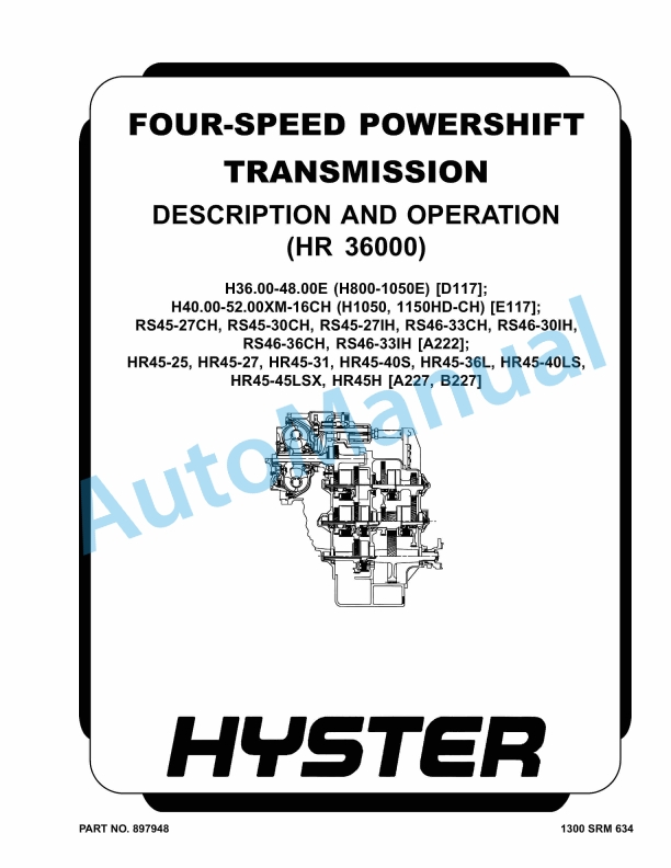
Hyster Four-Speed Powershift Transmission Description And Operation (HR 36000) Maintenance And Repair
$30.00
- Type Of Manual: Maintenance And Repair
- Number of Pages: 608
- Size: 18.6MB
- Format: PDF
Description
-
Model List:
- Four-Speed Powershift Transmission Description And Operation (HR 36000)
- 1. RM0634-(03-2005)-UK-EN_2
- 1.1. Four-Speed Powershift Transmission
- 1.2. Safety Precautions Maintenance and Repair
- 1.3. General
- 1.4. Automatic Powershift Control
- 1.5. Transmission Control System
- 1.6. Transmission Control Lever
- 1.7. Mechanical Description and Operation
- 1.8. General
- 1.9. Torque Converter
- 1.10. Description
- 1.11. Operation
- 1.12. Clutch Assemblies
- 1.13. Description
- 1.14. Operation
- 1.15. Transmission Operation in Neutral
- 1.16. Input Shaft, Forward Shaft, and Clutch Assembly
- 1.17. Description
- 1.18. Operation
- 1.19. Reverse, Second-Speed, and First-Speed Shaft and Clutch Assembli
- 1.20. Description
- 1.21. Operation
- 1.22. Third-Speed Shaft, Gear, and Clutch Assembly
- 1.23. Description
- 1.24. Operation
- 1.25. Fourth-Speed Shaft and Clutch
- 1.26. Description
- 1.27. Operation
- 1.28. Output Shaft
- 1.29. Description
- 1.30. Operation
- 1.31. Hydraulic Description and Operation
- 1.32. Sump, Filter, and Pump
- 1.33. Transmission Charge Pump
- 1.34. Pressure Regulator Valve
- 1.35. Relief Valve
- 1.36. Transmission Control Valve
- 1.37. Solenoid Valves
- 1.38. Direction Spools
- 1.39. Range Spools
- 1.40. Modulator Valves
- 1.41. Table 1. Solenoid Controls
- 2. RM0635-(06-2007)-UK-EN_2
- 2.1. Four-Speed Powershift Transmission
- 2.2. Safety Precautions Maintenance and Repair
- 2.3. General
- 2.4. Torque Converter Repair
- 2.5. Torque Converter, Remove
- 2.6. Torque Converter, Disassemble
- 2.7. Clean and Inspect
- 2.8. Torque Converter, Assemble
- 2.9. Torque Converter (Turbine) Housing, Disassemble
- 2.10. Relief Valve for Lube Pressure, Disassemble and Assemble
- 2.11. Oil Sealing Rings Sleeve, Replace
- 2.12. Torque Converter Housing, Assemble
- 2.13. Torque Converter, Install
- 2.14. Transmission Repair
- 2.15. Remove, Transmission Only
- 2.16. Transmission and Engine Assembly, Remove
- 2.17. Transmission, Disassemble
- 2.18. Output Shaft, Disassemble and Assemble
- 2.19. Fourth-Speed Shaft, Disassemble and Assemble
- 2.20. Third-Speed Shaft, Disassemble and Assemble
- 2.21. Forward Shaft and Clutch, Disassemble and Assemble
- 2.22. Reverse and Second-Speed Shaft and Clutch, Disassemble and Assem
- 2.23. First-Speed Shaft and Clutch, Disassemble and Assemble
- 2.24. Input Shaft, Disassemble and Assemble
- 2.25. Speed Sensor, Install
- 2.26. Transmission, Clean and Inspect
- 2.27. Transmission, Assemble
- 2.28. Control Valve
- 2.29. Clean and Inspect
- 2.30. Assemble and Install
- 2.31. Install, Transmission
- 2.32. Install, Transmission and Engine Assembly
- 2.33. Clean Oil System of Transmission After Major Repair
- 2.34. Automatic Powershift Control (APC 100)
- 2.35. Functional Description
- 2.36. Transmission Control Lever
- 2.37. First-Speed Shaft Bearings Adjustment
- 2.38. Torque Converter Stall Speed Check
- 2.39. Transmission Oil Pressures Check
- 2.40. Clutch Pressures Check
- 2.41. Torque Converter (Torque Converter Regulator) Oil Pressure Check
- 2.42. Troubleshooting
- 2.43. Transmission Controller (APC 100)
- 2.44. Table 1. Flange Nut Torque
- 2.45. Table 2. APC 100 Control Module (Pin Connections)
- 2.46. Table 3. Hobbs Gear Selector Connections
- 2.47. Table 4. Example Torque Values at Dimensions Shown
- 2.48. Table 5. Transmission Pressures
- 3. RM0047-(10-2011)-UK-EN
- 3.1. Planetary Gear Axle
- 3.2. Safety Precautions Maintenance and Repair
- 3.3. General
- 3.4. Description
- 3.5. Operation
- 3.6. Planetary Gear Axle Repair
- 3.7. Disassemble
- 3.8. Planetary Axle, Disassemble
- 3.9. Assemble and Install
- 3.10. Planetary Axle, Assemble
- 3.11. Torque Specifications
- 3.12. Troubleshooting
- 3.13. Table 1. Axle-to-Frame Fasteners
- 3.14. Table 2. Standard Torque Values for Axle Fasteners
- 3.15. Table 3. Drive Wheel Nut Torque
- 4. RM0046-(11-2014)-UK-EN_2
- 5. RM0231-(01-2016)-UK-EN_2
- 5.1. General
- 6. RM0776-(10-2014)-UK-EN_2
- 7. RM0786-(07-2006)-UK-EN
- 7.1. Steering System YardMaster
- 7.2. Safety Precautions Maintenance and Repair
- 7.3. General
- 7.4. Description
- 7.5. Steering Control Unit Repair
- 7.6. Description
- 7.7. Operation
- 7.8. Load-Sensing Steering
- 7.9. Disassemble
- 7.10. Assemble
- 7.11. Install
- 7.12. Steering Axle Repair
- 7.13. Description
- 7.14. Install
- 7.15. Steering Cylinder Repair
- 7.16. Clean and Inspect
- 7.17. Assemble
- 7.18. Install
- 7.19. Hubs Repair
- 7.20. Install
- 7.21. Spindles Repair
- 7.22. Install
- 7.23. System Air Removal
- 7.24. Relief Valve Adjustment for Steering System
- 7.25. Antitipping Device Adjustment
- 7.26. Troubleshooting
- 8. RM0783-(01-2004)-UK-EN
- 8.1. Hydraulic System YardMaster
- 8.2. Safety Precautions Maintenance and Repair
- 8.3. Description
- 8.4. Main Hydraulic Tank
- 8.5. Main Hydraulic Pump
- 8.6. Description
- 8.7. Load Sensing Pressure
- 8.8. Main Pump Controller
- 8.9. LS Servo
- 8.10. LS Control Valve
- 8.11. Power Servo
- 8.12. Load Sensing Pressure LS1
- 8.13. Load Sensing Pressure LS2
- 8.14. Standby Pressure
- 8.15. Power Control Valve
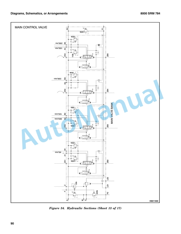
- 8.16. Main Control Valve
- 8.17. Description
- 8.18. Adjustment
- 8.19. Relief Pressures
- 8.20. Flow Control Settings
- 8.21. Derricking Down Speed
- 8.22. Derricking Up Speed
- 8.23. Telescoping Speeds
- 8.24. Steering
- 8.25. Description
- 8.26. Pilot System
- 8.27. Pilot Pump
- 8.28. Telescoping Retract Control Valve
- 8.29. Engine Radiator Fan Motor
- 8.30. Manipulator Pressure Valve
- 8.31. Engine Accelerator System
- 8.32. Joystick
- 8.33. Hydraulic Cooling System
- 8.34. Description
- 8.35. Brake Oil Cooling System
- 8.36. Description
- 8.37. Bar Relief Valve
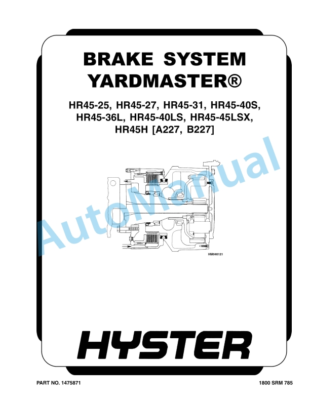
- 8.38. Service Brakes
- 8.39. Description
- 8.40. Parking Brake
- 8.41. Description
- 8.42. Table 1. Main Control Valve Torque Specifications
- 8.43. Table 2. Pressures in Relation to the Position of Solenoids and
- 9. RM0787-(11-2003)-UK-EN
- 9.1. Boom YardMaster
- 9.2. Safety Precautions Maintenance and Repair
- 9.3. Description and Operation
- 9.4. Hydraulic System
- 9.5. Derricking
- 9.6. Description
- 9.7. Derricking Up
- 9.8. Derricking Down
- 9.9. Holding Valve
- 9.10. Adjustments
- 9.11. Telescoping
- 9.12. Description
- 9.13. Telescoping Out (Extend)
- 9.14. Telescoping In (Retract)
- 9.15. Adjustments
- 9.16. Dampening
- 9.17. Description
- 9.18. Adjustment of the 4 bar ( 58 psi) Pressure Reducer
- 9.19. Boom Repair
- 9.20. Spreader
- 9.21. Install
- 9.22. Install
- 9.23. Dampening Cylinder
- 9.24. Install
- 9.25. Pivot Bearing
- 9.26. Removal
- 9.27. Install
- 9.28. Derricking Cylinder
- 9.29. Install
- 9.30. Disassemble
- 9.31. Clean, Inspect, and Repair
- 9.32. Assemble
- 9.33. Install
- 9.34. Telescoping Cylinder
- 9.35. Install
- 9.36. Shimming Key Clearance
- 9.37. Wear Pads
- 9.38. General
- 9.39. Side Wear Pads
- 9.40. Clean and Inspect
- 9.41. Install
- 9.42. Horizontal Front Wear Pads
- 9.43. Clean and Inspect
- 9.44. Install
- 9.45. Horizontal Rear Wear Pads
- 9.46. Clean and Inspect
- 9.47. Install
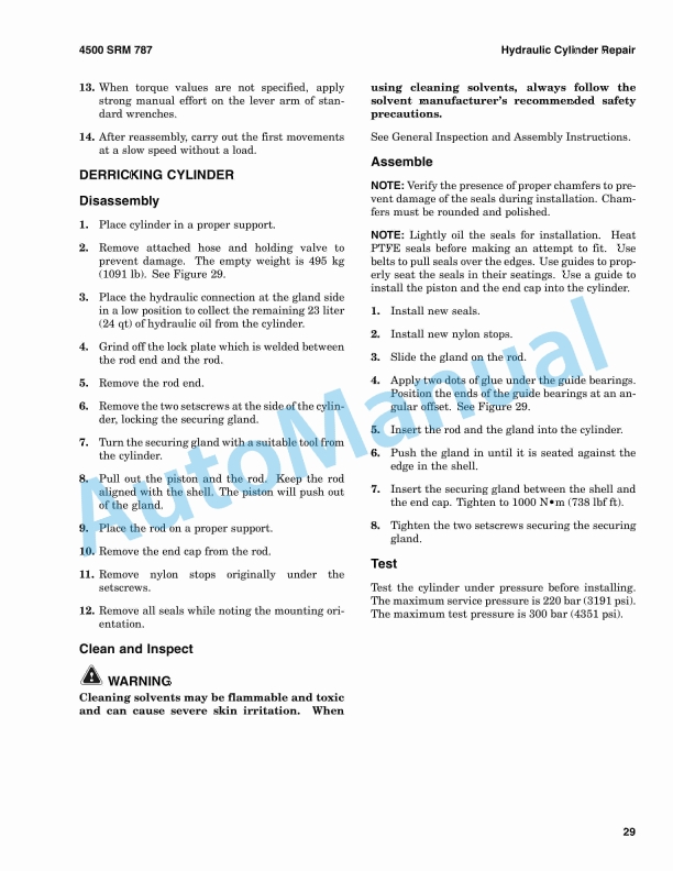
- 9.48. Hydraulic Cylinder Repair
- 9.49. General Inspection and Assembly Instructions
- 9.50. Derricking Cylinder
- 9.51. Disassembly
- 9.52. Clean and Inspect
- 9.53. Assemble
- 9.54. Telescoping Cylinder
- 9.55. Disassemble
- 9.56. Clean and Inspect
- 9.57. Assemble
- 9.58. Dampening Cylinder
- 9.59. Disassemble
- 9.60. Clean and Inspect
- 9.61. Assemble
- 10. RM0784-(03-2003)-UK-EN
- 10.1. Diagrams
- 10.2. Safety Precautions Maintenance and Repair
- 11. RM0780-(06-2005)-UK-EN
- 11.1. Periodic Maintenance YardMaster
- 11.2. Safety Precautions Maintenance and Repair
- 11.3. General
- 11.4. Serial Number Data
- 11.5. How to Move Disabled YardMaster
- 11.6. How to Tow YardMaster
- 11.7. How to Put YardMaster on Blocks
- 11.8. How to Raise Drive Tires
- 11.9. How to Raise Steering Tires
- 11.10. Maintenance Schedule
- 11.11. Daily Inspections
- 11.12. First Inspection After First 100 Hours of Operation
- 11.13. Periodic Maintenance Schedule
- 11.14. Boom Maintenance
- 11.15. Spreader Maintenance
- 11.16. PPM Spreader Maintenance
- 11.17. Maintenance Procedures Every 8 Hours or Daily
- 11.18. How to Make Checks With Engine Stopped
- 11.19. Tires and Wheels
- 11.20. Safety Labels
- 11.21. Fuel, Oil, or Coolant Leaks Check
- 11.22. Drive Belts
- 11.23. Battery
- 11.24. Engine Oil
- 11.25. Drain Water From Fuel Filter
- 11.26. Hydraulic System
- 11.27. Brake System Oil
- 11.28. Cooling System
- 11.29. Boom and Spreader
- 11.30. Hook, Winch, and Boom (HR45H)
- 11.31. How to Make Checks With Engine Running
- 11.32. Gauges, Indicator Lights, Horn, Circuit Breakers, and Relays
- 11.33. Air Filter
- 11.34. Air Conditioning
- 11.35. Control Levers and Pedals
- 11.36. Electrical System
- 11.37. Transmission Oil
- 11.38. Steering System
- 11.39. Service Brakes
- 11.40. Parking Brake
- 11.41. Engine Oil
- 11.42. Cooling System
- 11.43. Hydraulic System
- 11.44. Boom and Spreader Operation
- 11.45. Maintenance Procedures Every 50 Hours or Weekly
- 11.46. PPM Spreader
- 11.47. Rotator and Extension Transmissions
- 11.48. Rotator Motor
- 11.49. Rotator Assembly
- 11.50. Twist Locks
- 11.51. Wear Pads (Extension Beam)
- 11.52. Sideshift Cylinders
- 11.53. Maintenance Procedures Every 250 Hours or 6 Weeks
- 11.54. Engine Oil and Filter
- 11.55. Fuel Filter/Water Separator
- 11.56. Drive Belts
- 11.57. Steering Axle
- 11.58. Battery
- 11.59. Wheel Nuts
- 11.60. Winch Oil Level
- 11.61. Steering Axle Tie Rods and King Pins
- 11.62. Drive Shaft Joints
- 11.63. General Lubrication
- 11.64. ELME Spreader
- 11.65. Rotator and Extension Transmission
- 11.66. Rotator Assembly
- 11.67. Twist Locks
- 11.68. Maintenance Procedures Every 500 Hours or 3 Months
- 11.69. Air Filter
- 11.70. Hydraulic Oil Filters
- 11.71. Transmission Oil Filter
- 11.72. Differential and Wheel End Housings Oil
- 11.73. Hydraulic Tank Breather
- 11.74. Boom Horizontal Wear Pads
- 11.75. Boom Side Wear Pads
- 11.76. Sideshift Cylinder
- 11.77. Stop Cylinders (ELME Option)
- 11.78. ELME Sideshift Wear Pads
- 11.79. Wear Pads (Extension Beams)
- 11.80. Maintenance Procedures Every 1000 Hours or 6 Months
- 11.81. Coolant Filter
- 11.82. Hydraulic Accumulators
- 11.83. Brake Accumulator
- 11.84. Transmission Oil
- 11.85. Disc Brake
- 11.86. Inspect
- 11.87. Brake System Oil and Filter
- 11.88. Air Filter Primary Element
- 11.89. Hydraulic Tank Breather
- 11.90. PPM Spreader
- 11.91. Extension Beam Horizontal Pads
- 11.92. Extension Beam Side Wear Pads
- 11.93. Ring Gear Fixation Bolts
- 11.94. ELME Spreader
- 11.95. Wear Pads (Extension Cylinder)
- 11.96. Winch Oil
- 11.97. Pedals, Levers, Hinges, and Seat Rails (General Lubrication)
- 11.98. Maintenance Procedures Every 2000 Hours or Yearly
- 11.99. Engine Valve Adjustment
- 11.100. Hydraulic Relief Pressures
- 11.101. Counterweight Fixation
- 11.102. Load Sensing System
- 11.103. Door and Window Seals
- 11.104. Drive Axle and Differential Oil
- 11.105. Hydraulic Oil
- 11.106. Change Hydraulic Oil
- 11.107. Steer Wheel Hub Bearing Cavity
- 11.108. Brake System Oil and Filter
- 11.109. Rotor and Extension Transmission Fixation Bolts
- 11.110. Rotator and Extension Transmission Oil
- 11.111. Maintenance Procedures Every 6000 Hours or 2 Years
- 11.112. Engine Coolant
- 11.113. Vibration Damper
- 11.114. Twist Locks
- 11.115. Maintenance Procedures Every 8000 Hours
- 11.116. PPM Spreader
- 11.117. Wheel and Tire Replacement
- 11.118. Wheels, Remove
- 11.119. Remove Tire From Wheel
- 11.120. Install Tire on Wheel
- 11.121. Install Wheel in Tire
- 11.122. Add Air to Tires
- 11.123. Wheels, Install
- 11.124. General Maintenance
- 11.125. Spreader
- 11.126. Twist Locks
- 11.127. Rotator Assembly
- 11.128. How to Store YardMaster
- 11.129. Short-Term Storage
- 11.130. Long-Term Storage
- 11.131. How to Move YardMaster On Transport
- 11.132. Loading
- 11.133. Unloading
- 11.134. Preparation for Use
- 11.135. Preparation After Transport
- 11.136. Preparation After Storage
- 11.137. Table 1. Condition Check
- 11.138. Table 2. Fluid Level Check
- 11.139. Table 3. Checks With Engine Running
- 11.140. Table 4. Initial 100-Hour Inspection
- 11.141. Table 5. Inspect and Adjust
- 11.142. Table 6. Lubricate
- 11.143. Table 7. Change
- 11.144. Table 8. Inspect and Adjust
- 11.145. Table 9. Lubricate
- 11.146. Table 10. Initial 100-Hour Inspection
- 11.147. Table 11. Inspect and Adjust

%20Maintenance%20And%20Repair&url=https://pdfrepairmanual.com/docs/hyster-four-speed-powershift-transmission-description-and-operation-hr-36000-maintenance-and-repair/&media=https://pdfrepairmanual.com/wp-content/uploads/2026/01/hyster-four-speed-powershift-transmission-description-and-operation-hr-36000-maintenance-and-repair-1.jpg)
%20Service%20Manual&url=https://pdfrepairmanual.com/docs/hyster-b418-p1-6-p1-8-p2-0-p2-2-service-manual/&media=https://pdfrepairmanual.com/wp-content/uploads/2026/01/hyster-b418-p16-p18-p20-p22-service-manual-1.jpg)


%20Service%20Manual&url=https://pdfrepairmanual.com/docs/hyster-b174-r30es-service-manual/&media=https://pdfrepairmanual.com/wp-content/uploads/2026/01/hyster-b174-r30es-service-manual-1.jpg)
%20Service%20Manual&url=https://pdfrepairmanual.com/docs/hyster-c098-e70-120xl-service-manual/&media=https://pdfrepairmanual.com/wp-content/uploads/2026/01/hyster-c098-e70-120xl-service-manual-1.jpg)


%20Service%20Manual&url=https://pdfrepairmanual.com/docs/hyster-c004-s3-00-5-50e-service-manual/&media=https://pdfrepairmanual.com/wp-content/uploads/2026/01/hyster-c004-s300-550e-service-manual-1.jpg)
There are no reviews yet.