
Description
-
Model List:
- 830E-1AC Dump Truck
- 1. SAFETY RULES, TOOLS EQUIPMENT
- 1.1. SAFETY RULES
- 1.1.1. Use of TieOff Anchor During Maintenance and Repair
- 1.1.2. BODYUP RETENTION CABLE
- 1.2. NITROGEN CHARGING VALVE
- 1.3. ROLLOUT ASSEMBLY
- 1.4. SLEEVE ALIGNMENT TOOLS
- 1.5. QUICK DISCONNECT COUPLING
- 1.6. HARNESS
- 1.7. SEAL INSTALLATION RING
- 1.8. SOCKETS AND ADAPTERS
- 1.9. DUST CAPS
- 1.10. HYDRAULIC SYSTEM FLUSHING TOOLS
- 1.11. KOMVISION CALIBRATION TOOLS
- 1.12. MISCELLANEOUS SERVICE TOOLS
- 1.13. PAYLOAD DATA MANAGER
- 1.14. HYDRAULIC SYSTEM VACUUM PUMP
- 1.15. BRAKE PISTON TOOL
- 1.16. HIGH VOLTAGE TOOLS
- 1.17. VDC CUSTOM METER KIT (58B0600800)
- 1.18. BODY PAD SPACER TOOL
- 2. TRUCK COMPONENTS AND SPECIFICATIONS
- 2.1. Truck And Engine
- 2.2. AC Induction Traction Motorized Wheels
- 2.3. Suspension
- 2.4. Operators Cab
- 2.5. Power Steering
- 2.6. Dynamic Retarding
- 2.7. Brake System
- 3. SPECIFICATIONS
- 3.1. REAR AXLE COMPONENTS
- 4. FIELD WELDING FOR ASSEMBLY OR REPAIR
- 4.1. WELDER QUALIFICATION AND TRAINING
- 4.2. WELD PROCEDURES
- 4.3. APPROVED CONSUMABLES
- 4.4. WELD QUALITY REQUIREMENTS
- 4.5. MATERIALS, CONTROLS, AND PRECAUTIONS
- 4.6. WELD INSPECTION
- 4.7. RECORDS
- 4.8. ANNEX A
- 4.9. ANNEX B
- 4.9.1. TOE HAMMER PEENING
- 4.9.1.1. Procedure
- 4.9.2. TOE GRINDING WITH A ROTARY BURR
- 4.9.2.1. Procedure
- 4.10. BIBLIOGRAPHY
- 4.10.1. SPECIAL PRECAUTIONS WHEN SERVICING AN AC DRIVE SYSTEM TRUCK
- 4.10.1.1. Engine Shutdown Procedure before Welding or Performing Maintenance
- 5. RECEIVING ASSEMBLY PREPARATION
- 5.1. Preparation
- 5.1.1. Inspection, Cleaning, Setup
- 5.1.2. Color Coded Boxes
- 5.2. ASSEMBLY LAYOUT
- 6. CHASSIS ASSEMBLY
- 6.1. RECOMMENDED ASSEMBLY DATA
- 6.2. BASIC ASSEMBLY PROCEDURE
- 6.2.1. ORDER OF ASSEMBLY
- 6.2.2. LEVEL 1
- 6.2.3. LEVEL 2
- 6.2.4. LEVEL 7
- 6.3. GENERAL PRECAUTIONS AND INSTRUCTION
- 6.3.1. Angle Advance Tightening Procedure
- 6.3.2. Upper Mounting Joint 60 Advance
- 6.3.3. Lower Mounting Joint 90 Advance
- 6.3.4. Inspection
- 6.4. GENERAL INFORMATION
- 6.5. BODY ASSEMBLY
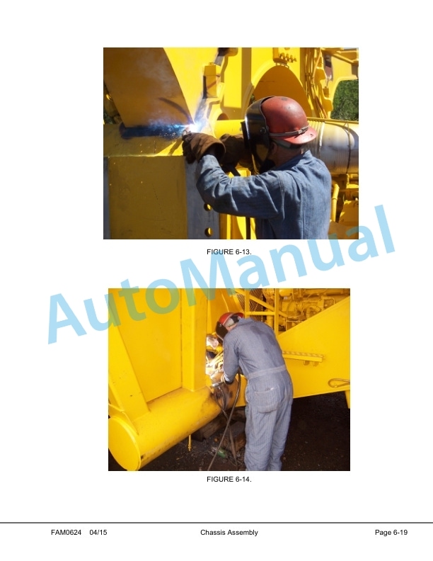
- 6.6. BODY WELDING
- 7. FINAL ASSEMBLY
- 7.1. Body Pad Shimming Procedure
- 8. APPENDIX
- 8.1. LUBRICATION CHART
- 9. OILING AND CHARGING PROCEDURE
- 9.1. GENERAL
- 9.2. EQUIPMENT LIST
- 9.3. HYDRAIR CHARGING KIT
- 9.3.1. Installation of Charging Kit
- 9.3.2. Removal of Charging Kit
- 9.4. SUPPORT BLOCKS FOR OILING AND CHARGING DIMENSIONS
- 9.5. FRONT SUSPENSION
- 9.5.1. Front Suspension Oiling
- 9.5.2. Front Suspension Nitrogen Charging
- 9.6. REAR SUSPENSION
- 9.6.1. Rear Suspension Oiling
- 9.6.2. Rear Suspension Nitrogen Charging
- 10. OIL AND NITROGEN SPECIFICATIONS CHART
- 11. TOEIN ADJUSTMENT
- 12. AUTO LUBE SYSTEM
- 12.1. Lincoln Flow master Phase I Auto Lube System with fixed Hydraulic Controls
- 12.2. Lube Pump Startup / Purging Procedure
- 12.3. Truck Lube System Purging Procedure After lube pump has been primed with grease.
- 12.4. INJECTOR SETTINGS
- 12.5. TIMER
- 12.6. WARNING SYSTEM
- 13. AIR CONDITIONING SYSTEM CHECKOUT PROCEDURE
- 14. KOMTRAX PLUS SETUP PROCEDURE
- 14.1. Purpose
- 14.2. Preliminary Procedures
- 14.3. Necessary Equipment
- 14.4. Check for KOMTRAX Plus System Faults
- 14.5. KOMTRAX Plus Setup
- 14.6. Begin KOMTRAX Plus Setup
- 15. KOMTRAX PLUS CHECKOUT PROCEDURE
- 15.1. Purpose
- 15.2. Preliminary Procedures
- 15.3. Necessary Equipment
- 15.4. Check for KOMTRAX Plus System Faults
- 15.5. Checkout Procedure
- 16. IM CHECKOUT 830E1AC WITH DIGITAL DISPLAY
- 16.1. Purpose
- 16.2. Necessary Equipment
- 16.3. Install the application code
- 16.4. How to use the IM Realtime Data Monitor Software
- 16.5. Check for Fault Codes Associated with the Interface Module.
- 16.6. Interface Module I/O
- 16.7. Check Digital Inputs to the Interface Module
- 16.8. Check Analog Inputs to the Interface Module
- 16.9. Check Serial Interfaces to the IM
- 16.10. Check Outputs from the Interface Module
- 17. PAYLOAD METER IV CHECKOUT PROCEDURE
- 17.1. Necessary Equipment
- 17.2. Install the Application Code
- 17.3. General Instructions
- 17.4. Appendix A
- 17.4.1. Guide to Connect to Payload Meter IV
- 17.4.2. Configuring a PCs Static IP Address
- 17.5. Appendix B
- 17.5.1. Installing Payload Meter IV Truck Application Software via USB
- 17.6. Payload Meter IV Checkout Procedure Confirmation
- 18. Electric Checkout Procedure
- 18.1. Scope
- 18.2. General Description
- 18.3. General Precautions
- 18.4. Normal shutdown procedure
- 18.5. AC Drive System Description
- 18.6. Test equipment needed to fully test AC system
- 18.7. Visual Inspection
- 18.8. Resistance Check Preparation
- 18.9. Resistance Check
- 18.10. Voltage Check
- 18.11. Key Switch OFF Checks
- 18.12. Key Switch ON Check
- 18.13. GE Control Switch ON Check
- 18.14. Truck Function Check
- 18.15. Key Switch OFF
- 18.16. Key Switch ON
- 18.17. Interface Module (IM) System
- 18.18. Komtrax Plus (VHMS) Checkout
- 18.19. Payload Meter Checkout
- 18.20. GE Vehicle Test Instructions (VTI)
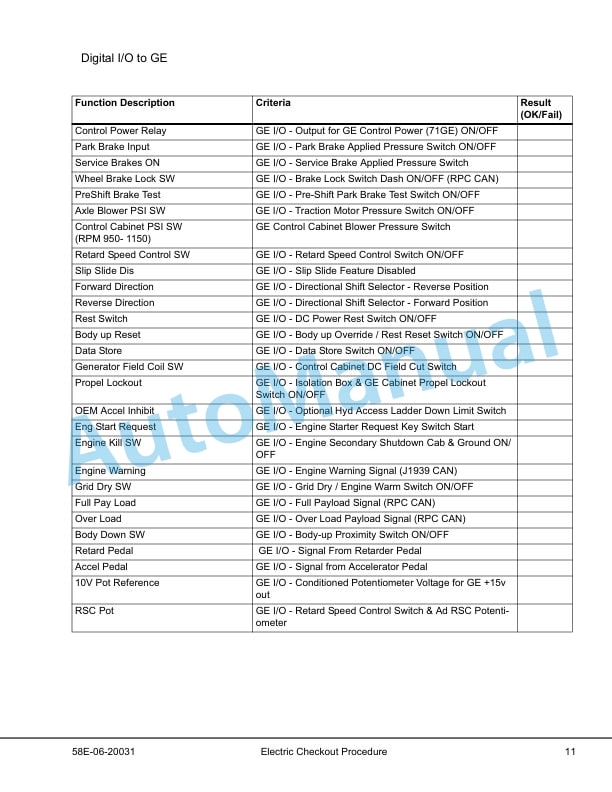
- 18.21. Digital I/O to GE
- 18.22. Engine Shutdown Smart Timer Check
- 18.23. Body Hoist Limit
- 18.24. Truck Function Check
- 19. RESERVE OIL SYSTEM R2000DF W/AUTO FILL
- 19.1. AFC Control StartUp / Fast Fill Procedure
- 19.2. Reserve pump R2000DF startup and led description.
- 20. AUTOMATIC LUBRICATION SYSTEM
- 20.1. GENERAL DESCRIPTION
- 20.2. SYSTEM COMPONENTS
- 20.2.1. Filter
- 20.2.2. Hydraulic Motor and Pump
- 20.2.3. Grease Reservoir
- 20.2.4. Pressure Reducing Valve
- 20.2.5. Flow Control Valve
- 20.2.6. Solenoid Valve
- 20.2.7. Vent Valve
- 20.2.8. Over Pressure Cut Off Switch
- 20.2.9. Grease Pressure Failure Switch
- 20.2.10. Injectors
- 20.2.11. Interface Module
- 20.2.12. Relief Valve (unloader valve)
- 20.3. SYSTEM OPERATION
- 20.3.1. Normal Operation
- 20.3.2. Lubricant Required For System
- 20.3.3. Filter Assembly
- 20.4. LUBRICANT PUMP
- 20.4.1. Pump Housing Oil Level
- 20.4.2. Pump Pressure Control
- 20.5. SYSTEM CHECKOUT
- 20.5.1. Lubrication Cycle Operation
- 21. SYSTEM TROUBLESHOOTING CHART
- 22. STANDARD TORQUE CHARTS AND CONVERSION TABLES
- 22.1. EFFECT OF SPECIAL LUBRICANTS On Fasteners and Standard Torque Values
- 22.2. STANDARD ASSEMBLY TORQUES For 12Point, Grade 9 Capscrews (SAE)
- 22.3. STANDARD ASSEMBLY TORQUES For Class 10.9 Capscrews Class 10 Nuts
- 23. HYDRAULIC SYSTEM FLUSHING PROCEDURE
- 23.1. SYSTEM FLUSHING
- 23.1.1. Hydraulic System Flushing Procedure
- 24. STATIC BRAKE SYSTEM CHECKOUT
- 24.1. STATIC BRAKE SYSTEM CHECKOUT
- 24.1.1. Events
- 24.1.2. OPERATION
- 24.1.2.1. Description
- 24.1.2.2. Brake Test Exit Criteria
- 24.1.3. PERFORMING THE BRAKE TESTS
- 24.1.3.1. Setup
- 24.1.3.2. Service Brake Test
- 24.1.3.3. Parking Brake Test
- 24.1.3.4. Retard System Test
- 25. KOMVISION CHECKOUT PROCEDURE
- 25.1. Necessary Equipment
- 25.2. STEP 1 Settings
- 26. Wireless Bridge Checkout procedure
- 26.1. Purpose
- 26.2. Necessary Equipment
- 26.3. Communication Setup
- 26.4. Appendix A
- 26.5. Setting The Computer Subnet Mask And IP Address
- 26.6. Windows 2000
- 26.7. Windows XP
- 26.8. Windows Vista
- 26.9. Windows 7
- 26.10. Appendix B Troubleshooting



There are no reviews yet.