
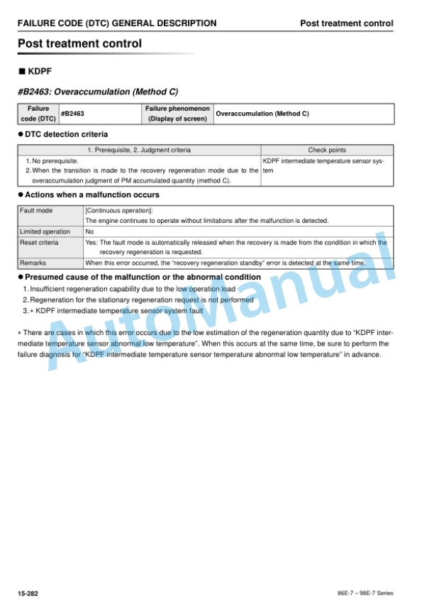
Description
-
Model List:
- 86E-7 Series Diesel Engine
- 98E-7 Series Diesel Engine
- 1. COVER
- 2. Table of Contents
- 3. STRUCTURE AND FUNCTION,TESTING AND ADJUSTING,DISASSEMBLY AND ASSEMBLY,AND MAINTENANCE STANDARD
- 3.1. Introduction
- 3.2. APPLICABLE MACHINE
- 3.3. Safety
- 3.3.1. Safety Statements
- 3.3.2. Safety Precautions
- 3.4. General Service Information
- 3.4.1. Component Identification
- 3.4.2. Function of Major Engine Components
- 3.4.3. Function of Cooling System Components
- 3.4.4. Main Electronic Control Components and Features
- 3.4.5. Installation Position of Sensors
- 3.4.6. Diesel Fuel
- 3.4.7. Engine Oil
- 3.4.8. Engine Coolant
- 3.4.9. Specifications
- 3.4.10. Principal Engine Specifications
- 3.4.11. Engine Service Standards
- 3.4.12. Tightening Torques for Standard Bolts and Nuts
- 3.4.13. Abbreviations and Symbols
- 3.4.14. Unit Conversions
- 3.5. Periodic Maintenance
- 3.5.1. Before You Begin Servicing
- 3.5.2. Introduction
- 3.5.3. Periodic Maintenance Schedule
- 3.5.4. Periodic Maintenance Procedures
- 3.6. Engine
- 3.6.1. Before You Begin Servicing
- 3.6.2. Introduction
- 3.6.3. Cylinder Head Specifications
- 3.6.4. Camshaft and Timing Gear Train Specifications
- 3.6.5. Crankshaft and Piston Specifications
- 3.6.6. Cylinder Block Specifications
- 3.6.7. Special Torque Chart
- 3.6.8. Special Service Tools
- 3.6.9. Measuring Instruments
- 3.6.10. Cylinder Head
- 3.6.11. Measuring and Adjusting Valve Clearance
- 3.6.12. Crankshaft and Camshaft Components
- 3.6.13. EGR System
- 3.6.14. Intake Throttle
- 3.7. Fuel System
- 3.7.1. Before You Begin Servicing
- 3.7.2. System Structure
- 3.7.3. Fuel System Specifications
- 3.7.4. Fuel System Diagram
- 3.7.5. Fuel System Components
- 3.8. Cooling System
- 3.8.1. Before You Begin Servicing
- 3.8.2. Introduction
- 3.8.3. Cooling System Diagram
- 3.8.4. Engine Coolant Pump Components
- 3.8.5. Engine Coolant System Check
- 3.8.6. Engine Coolant Pump
- 3.9. Lubrication System
- 3.9.1. Before You Begin Servicing
- 3.9.2. Introduction
- 3.9.3. Oil Pump Service Information
- 3.9.4. Lubrication System Diagram
- 3.9.5. Checking Engine Oil Pressure
- 3.9.6. Oil Pump Components
- 3.10. Turbocharger
- 3.10.1. Before You Begin Servicing
- 3.10.2. Introduction
- 3.10.3. Specifications
- 3.10.4. Troubleshooting
- 3.10.5. Turbocharger Components
- 3.10.6. Turbocharger Component Functions
- 3.10.7. Washing Procedure
- 3.10.8. Periodic Inspection
- 3.11. Starter Motor
- 3.11.1. Before You Begin Servicing
- 3.11.2. Introduction
- 3.11.3. Starter Motor Information
- 3.11.4. Starter Motor Specifications
- 3.11.5. Starter Motor Troubleshooting
- 3.11.6. Starter Motor Components
- 3.11.7. Starter Motor
- 3.12. Alternator
- 3.12.1. Before You Begin Servicing
- 3.12.2. Introduction
- 3.12.3. Dynamo and Alternator Information
- 3.12.4. Alternator Specifications
- 3.12.5. Dynamo Specifications
- 3.12.6. Alternator Troubleshooting
- 3.12.7. Alternator Components
- 3.12.8. Alternator Wiring Diagram
- 3.12.9. Alternator Standard Output
- 3.12.10. Alternator
- 3.12.11. Dynamo Component Location
- 3.12.12. Dynamo Wiring Diagram
- 3.12.13. Operation of Dynamo
- 3.12.14. Dynamo Standard Output
- 3.12.15. Testing of Dynamo
- 3.12.16. Dynamo
- 3.13. Electronic Control System
- 3.13.1. Before You Begin Servicing
- 3.13.2. System Structure
- 3.13.3. How to Remove and Reattach the Diesel Particulate Filter (KDPF)
- 3.13.4. SF and KDPF Maintenance Kit
- 3.13.5. Troubleshooting of Electronic Control System
- 3.13.6. Replacement of Components
- 3.14. Electric Wiring
- 3.14.1. Electric Wiring Precautions
- 3.14.2. Electrical Wire Resistance
- 3.14.3. Battery Cable Resistance
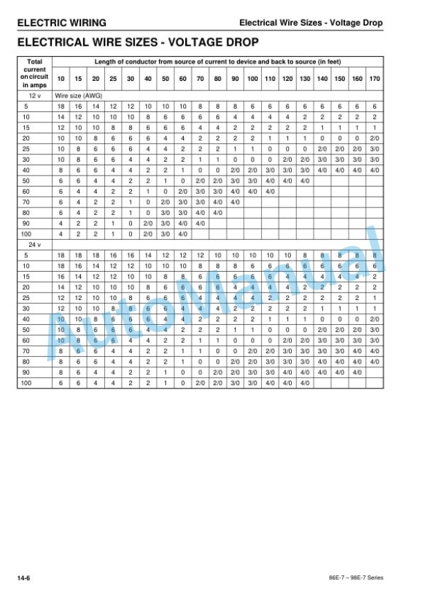
- 3.14.4. Electrical Wire Sizes Voltage Drop
- 3.14.5. Conversion of AWG to European Standards
- 4. TROUBLESHOOTING
- 4.1. FAILURE CODE (DTC) GENERAL DESCRIPTION
- 4.1.1. Failure code (DTC) list
- 4.1.2. Description
- 4.1.3. Sensor related
- 4.1.4. Contact output related
- 4.1.5. CRS (common rail system) related
- 4.1.6. Actuator
- 4.1.7. Communication related
- 4.1.8. ECU related
- 4.1.9. Contact input related
- 4.1.10. Post treatment control
- 4.1.11. Others
- 4.2. METHOD AND PROCEDURE OF FAILURE DIAGNOSIS
- 4.2.1. Description
- 4.2.2. Sensor related
- 4.2.3. Contact output related
- 4.2.4. Contact input related
- 4.2.5. CRS (common rail system) related
- 4.2.6. Actuator
- 4.2.7. Communication related
- 4.2.8. ECU related
- 4.2.9. Others
- 4.3. MECHANICAL SYSTEMFAILURE DIAGNOSIS
- 4.3.1. Special Service Tools
- 4.3.2. Tier 4 (BOSCH) Compression Inspection Procedures
- 4.3.3. Measured Value and Troubleshooting
- 4.3.4. Quick Reference Table for Troubleshooting


There are no reviews yet.