
Description
-
Model List:
- 95E-5 Series Engine
- 1. SEN0435700 WA906, WA100M6
- 2. Index and foreword
- 2.1. Index
- 2.1.1. Composition of shop manual
- 2.1.2. Table of contents
- 2.2. Foreword and general information
- 2.2.1. Safety notice
- 2.2.2. How to read the shop manual
- 2.2.3. Explanation of terms for maintenance standard
- 2.2.4. Handling of electric equipment and hydraulic component
- 2.2.5. Handling of connectors newly used for engines
- 2.2.6. How to read electric wire code
- 2.2.7. Precautions when carrying out operation
- 2.2.8. Method of disassembling and connecting pushpull type coupler
- 2.2.9. Standard tightening torque table
- 2.2.10. Conversion table
- 3. Specification
- 3.1. Specification and technical data
- 3.1.1. Outline
- 3.1.2. Specifications
- 3.1.3. General view
- 3.1.4. Weight table
- 3.1.5. Engine performance curves
- 4. Structure, function and maintenance standard
- 4.1. Structure, function and maintenance standard, Part 1
- 4.1.1. General structure
- 4.1.2. Air intake and exhaust system
- 4.1.2.1. Air intake and exhaust unit
- 4.1.2.2. Main moving parts
- 4.1.2.3. Crankshaft
- 4.1.2.4. Camshaft
- 4.1.2.5. Piston, piston ring and piston pin
- 4.1.2.6. Connecting rod
- 4.1.2.7. Flywheel and flywheel housing
- 4.1.2.8. Timing gear
- 4.1.2.9. Valve system
- 4.1.2.10. Valve, valve guide
- 4.1.2.11. Rocker arm shaft, push rod and tappet
- 4.2. Structure, function and maintenance standard, Part 2
- 4.2.1. Lubrication system
- 4.2.1.1. Lubrication system diagram
- 4.2.1.2. Oil pump
- 4.2.1.3. Regulator valve
- 4.2.1.4. Oil filter
- 4.2.2. Fuel system
- 4.2.2.1. Fuel system diagram
- 4.2.2.2. Supply pump
- 4.2.2.3. Fuel injection nozzle
- 4.2.2.4. Fuel filter
- 4.2.2.5. Common rail
- 4.2.2.6. Various sensor
- 4.2.3. Cooling system
- 4.2.3.1. Cooling system diagram
- 4.2.3.2. Water pump
- 4.2.3.3. Cooling fan drive and thermostat
- 4.2.4. Electrical equipment
- 4.2.4.1. Starting and charging system electrical circuit diagram
- 4.2.4.2. Alternator
- 4.2.4.3. Starting motor
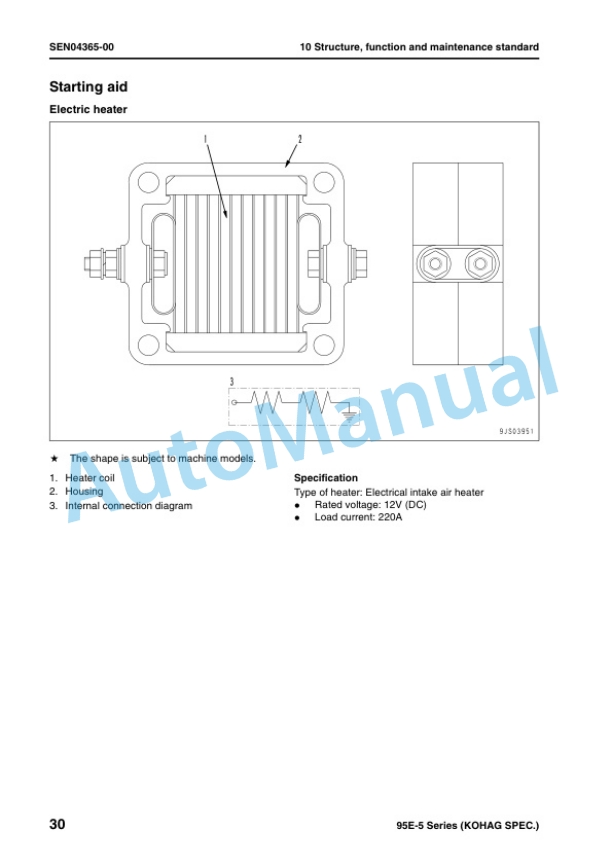
- 4.2.4.4. Starting aid
- 4.2.4.5. Engine controller
- 5. Standard value table
- 5.1. Standard service value table
- 5.1.1. Standard service value table for testing, adjusting, and troubleshooting
- 5.1.2. Runningin standard and performance test standard
- 6. Testing and adjusting
- 6.1. Testing and adjusting
- 6.1.1. Testing and adjusting tools list
- 6.1.2. Measuring intake air pressure
- 6.1.3. Testing exhaust temperature
- 6.1.4. Adjusting valve clearance
- 6.1.5. Testing compression pressure
- 6.1.6. Testing blowby pressure
- 6.1.7. Testing oil pressure
- 6.1.8. Handling fuel system parts
- 6.1.9. Releasing residual pressure in fuel system
- 6.1.10. Testing fuel pressure
- 6.1.11. Reduced cylinder mode operation
- 6.1.12. Noinjection cranking
- 6.1.13. Testing leakage from pressure limiter and return rate from injector
- 6.1.14. Bleeding air from fuel circuit
- 6.1.15. Testing fuel system for leakage
- 6.1.16. Testing and adjusting alternator belt tension
- 6.1.17. Handling controller voltage circuit
- 7. Troubleshooting
- 7.1. General information on troubleshooting
- 7.1.1. Points on troubleshooting
- 7.1.2. Error code and failure code table
- 7.1.3. Information in troubleshooting table
- 7.2. Troubleshooting of electrical system (Emode), Part 1
- 7.2.1. E1 Code 111/CA111 ECM Critical Internal Failure
- 7.2.2. E2 Code 115/CA115 Eng. Ne and Bkup Speed Sensor Error
- 7.2.3. E3 Code 122/CA122 Charge Air Press Sensor High Error
- 7.2.4. E4 Code 123/CA123 Charge Air Press Sensor Low Error
- 7.2.5. E5 Code 131/CA131 Throttle Sensor High Error
- 7.2.6. E6 Code 132/CA132 Throttle Sensor Low Error
- 7.2.7. E7 Code 144/CA144 Coolant Temp. Sensor High Error
- 7.2.8. E8 Code 145/CA145 Coolant Temp. Sensor Low Error
- 7.2.9. E9 Code 153/CA153 Charge Air Temp. Sensor High Error
- 7.2.10. E10 Code 154/CA154 Charge Air Temp. Sensor Low Error
- 7.2.11. E11 Code 187/CA187 Sensor Sup. 2 Volt. Low Error
- 7.2.12. E12 Code 221/CA221 Ambient Air Press. Sensor High Error
- 7.2.13. E13 Code 222/CA222 Ambient Air Press. Sensor Low Error
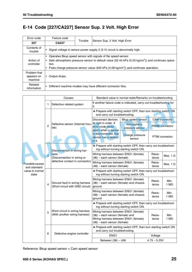
- 7.2.14. E14 Code 227/CA227 Sensor Sup. 2 Volt. High Error
- 7.2.15. E15 Code 234/CA234 Eng. Overspeed
- 7.2.16. E16 Code 238/CA238 Ne Speed Sensor Sup. Volt. Error
- 7.2.17. E17 Code 271/CA271 IMV Short Error
- 7.2.18. E18 Code 272/CA272 IMV Open Error
- 7.2.19. E19 Code 322/CA322 Injector 1 (L/B 1) System Open/Short Error
- 7.2.20. E20 Code 324/CA324 Injector 3 (L/B 3) System Open/Short Error
- 7.2.21. E21 Code 331/CA331 Injector 2 (L/B 2) System Open/Short Error
- 7.2.22. E22 Code 332/CA332 Injector 4 (L/B 4) System Open/Short Error
- 7.2.23. E23 Code 351/CA351 INJ. Drive Circuit Error
- 7.2.24. E24 Code 352/CA352 Sensor Sup. 1 Volt. Low Error
- 7.2.25. E25 Code 386/CA386 Sensor Sup. 1 Volt. High Error
- 7.2.26. E26 Code 431/CA431 Idle Validation SW Low error
- 7.2.27. E27 Code 432/CA432 Idle Validation Process error
- 7.2.28. E28 Code 435/CA435 Abnormality in engine oil pressure switch
- 7.2.29. E29 Code 441/CA441 Battery voltage low error
- 7.2.30. E30 Code 442/CA442 Battery voltage high error
- 7.3. Troubleshooting of electrical system (Emode), Part 2
- 7.3.1. E31 Code 449/CA449 Rail Press. Very High Error
- 7.3.2. E32 Code 451/CA451 Rail Press. Sensor High Error
- 7.3.3. E33 Code 452/CA452 Rail Press. Sensor Low Error
- 7.3.4. E34 Code 553/CA553 Rail Press. High Error
- 7.3.5. E35 Code 559/CA559 Rail Press. Low Error
- 7.3.6. E36 Code 689/CA689 Eng. Ne Speed Sensor Error
- 7.3.7. E37 Code 731/CA731 Eng. Bkup Speed Sensor Phase Error
- 7.3.8. E38 Code 757/CA757 All Persistent Data Lost Error
- 7.3.9. E39 Code 778/CA778 Eng. Bkup Speed Sensor Error
- 7.3.10. E40 Code 1633/CA1633 KOMNET Dtalink Timeout Error
- 7.3.11. E41 Code 2185/CA2185 Throttle Sens. Sup. Volt. High Error
- 7.3.12. E42 Code 2186/CA2186 Throttle Sens. Sup. Volt. Low Error
- 7.3.13. E43 Code 2249/CA2249 Rail Press. Very Low Error
- 7.3.14. E44 Code 2311/CA2311 Abnormality in IMV solenoid
- 7.3.15. E45 Code 2555/CA2555 Grid Heater Relay Volt. Low Error
- 7.3.16. E46 Code 2556/CA2556 Grid Heater Relay Volt. High Error
- 7.3.17. E47 Code ( )/BBAZG Eng. Oil press. Low Speed Derate
- 7.3.18. E48 Code ( )/BBAZG Eng. Oil press. Torque Derate
- 7.3.19. E49 Code ( )/BBCNS Eng. Overheat
- 7.4. Troubleshooting of mechanical system (Smode)
- 7.4.1. Method of using troubleshooting charts
- 7.4.2. S1 Starting performance is poor
- 7.4.3. S2 Engine does not start
- 7.4.4. S3 Engine does not pick up smoothly
- 7.4.5. S4 Engine stops during operations
- 7.4.6. S5 Engine does not rotate smoothly
- 7.4.7. S6 Engine lacks output (or lacks power)
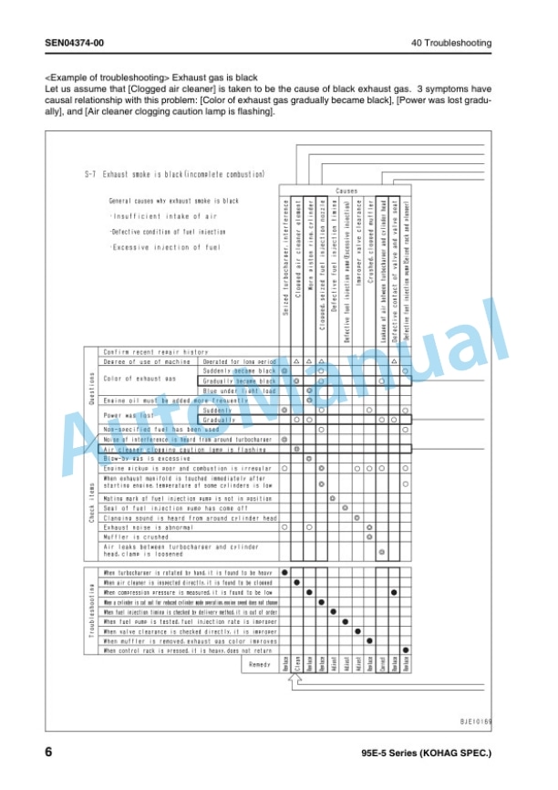
- 7.4.8. S7 Exhaust smoke is black (incomplete combustion)
- 7.4.9. S8 Oil consumption is excessive (or exhaust smoke is blue)
- 7.4.10. S9 Oil becomes contaminated quickly
- 7.4.11. S10 Fuel consumption is excessive
- 7.4.12. S11 Oil is in coolant (or coolant spurts back or coolant level goes down)
- 7.4.13. S12 Oil pressure drops
- 7.4.14. S13 Oil level rises (Entry of coolant or fuel)
- 7.4.15. S14 Coolant temperature becomes too high (overheating)
- 7.4.16. S15 Abnormal noise is made
- 7.4.17. S16 Vibration is excessive
- 8. Disassembly and assembly
- 8.1. General information on disassembly and assembly
- 8.1.1. How to read this manual
- 8.1.2. Coating materials list
- 8.1.3. Special tools list
- 8.2. Disassembly and assembly, Part 1
- 8.2.1. General disassembly of engine
- 8.3. Disassembly and assembly, Part 2
- 8.3.1. General assembly of engine
- 8.4. Disassembly and assembly, Part 3
- 8.4.1. Disassembly and assembly procedure for fuel supply pump unit
- 8.4.2. Disassembly and assembly procedure for oil seal units


There are no reviews yet.