
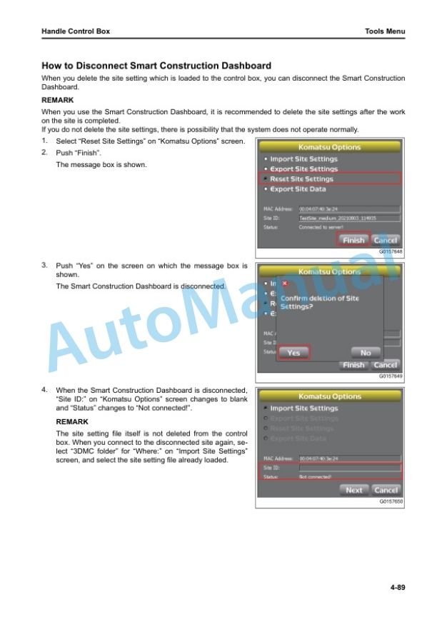
Description
-
Model List:
- D155AXi-8 Bull Dozer
- 1. Cover
- 2. Foreword
- 2.1. Table of Contents
- 2.2. Read This Manual
- 2.3. Safety Information
- 2.4. Introduction
- 2.4.1. intelligent Machine Control
- 2.4.2. Machine Features
- 2.5. Abbreviation List
- 3. Safety
- 3.1. General Precautions Common to Operation and Maintenance
- 3.1.1. Precautions When You Get on or Off Machine
- 3.1.1.1. Precautions When You Stand Up from Operators Seat
- 3.1.1.2. Precautions When You Move Away from Operator Seat
- 3.1.2. Precautions for Blade Automatic Control
- 3.2. Precautions for Operation
- 3.2.1. Start Engine
- 3.2.1.1. In Cold Weather
- 3.3. Precautions for Maintenance
- 3.3.1. Precautions for Check and Maintenance
- 3.3.1.1. Precautions When You Discard Waste Materials
- 3.3.1.2. Precautions for GNSS Antenna
- 3.3.1.3. Handle Component Which Contains Mercury
- 3.4. Precautions for DEF
- 3.4.1. General Character and Precautions for Handling
- 3.4.2. Precautions When You Add
- 4. Operation
- 4.1. General View
- 4.1.1. Names of Machine Equipment
- 4.1.2. Machine Outside Equipment Name
- 4.1.3. Control Levers and Pedals
- 4.1.3.1. Control Box Name
- 4.2. Explanation of Components
- 4.2.1. intelligent Machine Control System
- 4.2.1.1. Control Box
- 4.2.1.2. Network Modem
- 4.2.1.3. Auto/Manual Switch
- 4.2.1.4. Cut/Fill Offsets Switch
- 4.2.1.5. Back Grade Mode Switch
- 4.2.1.6. GNSS Antenna
- 4.2.1.7. GNSS Receiver
- 4.2.1.8. AutoPitch
- 4.2.2. Other Equipment
- 4.2.2.1. Remove and Install Control Box
- 4.3. Machine Operations and Controls
- 4.3.1. Checks and Adjustment Before You Start Engine
- 4.3.2. Operations and Checks After You Start Engine
- 4.3.2.1. Reset Cylinder Stroke End
- 4.3.2.2. Set Standard Angle of Blade Edge
- 4.3.3. How to Stop Engine
- 4.3.4. How to Use Automatic Blade Control
- 4.3.4.1. Prepare for Blade Automatic Control
- 4.3.4.2. Handle Automatic Blade Control
- 4.3.4.3. Mode Settings
- 4.3.4.4. Function Related with Machine Monitor Blade Automatic Control
- 4.3.4.5. Precautions When You Use Blade Automatic Control
- 4.3.4.6. Recommended Applications and Modes
- 4.4. Transportation
- 4.4.1. Handle Cylinders When Blade is Not Installed or Removing and Installing Blade
- 4.4.2. Remove Radio Device Antenna Cable
- 4.4.3. How to Remove Bracket for GNSS Antenna
- 4.5. Precautions for LongTerm Storage
- 4.5.1. Turn Battery Disconnect Switch to OFF Position Before LongTerm Storage
- 4.6. Troubles and Procedures
- 4.6.1. Other Trouble
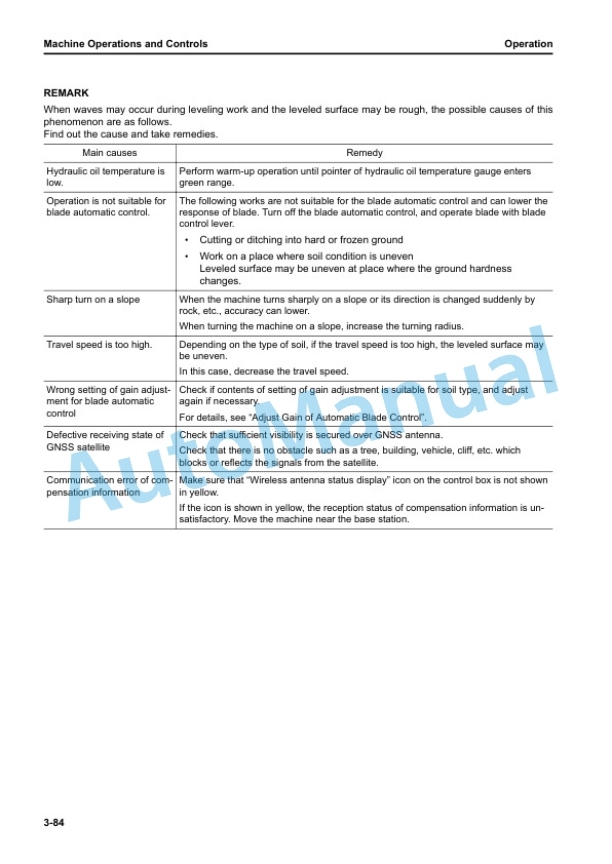
- 4.6.1.1. Phenomena and Procedures for Control Box
- 5. Handle Control Box
- 5.1. Table of Contents
- 5.2. Overview
- 5.2.1. Function of Switches
- 5.2.1.1. Power ON/OFF and Menu Switch
- 5.2.1.2. Zoom in Switch
- 5.2.1.3. Zoom Out Switch
- 5.2.1.4. Toggle Main View Switch
- 5.2.2. Brightness and Volume Control
- 5.2.3. LED Indicator
- 5.2.4. Keyboard Functions
- 5.2.4.1. How to Input with Alphanumeric Keyboard
- 5.2.4.2. How to Input with Numeric Keyboard
- 5.2.5. How to Show Main Menu
- 5.3. File Menu
- 5.3.1. Project Files
- 5.3.1.1. How to Import and Set Project Files
- 5.3.1.2. How to Make Project File
- 5.3.1.3. How to Export Project File
- 5.3.2. Control Point Files
- 5.3.2.1. How to Import Control Point Files
- 5.3.3. Layers
- 5.3.3.1. How to Import Layers
- 5.3.4. Point Data
- 5.3.4.1. How to Register Point Data
- 5.3.5. Surface File
- 5.3.5.1. How to Import Surface Files
- 5.3.5.2. How to Make Flat Surface Files
- 5.3.5.3. How to Make Sloping Surface Files
- 5.3.5.4. Make Crown Road Surface File
- 5.3.5.5. How to Make Triangulated Surfaces from Topo Survey File
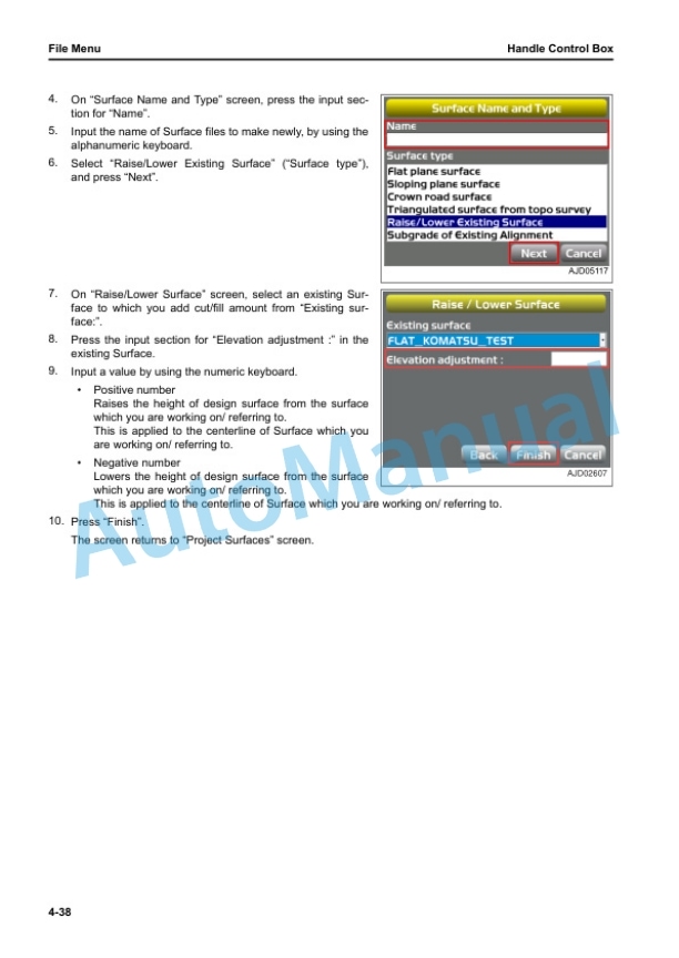
- 5.3.5.6. How to Make Surface Files After You Reflect Raise or Lower Quantity of an Existing Surface
- 5.3.5.7. How to Make Alignment File of Subgrade of Active Alignment
- 5.3.6. Active File
- 5.3.6.1. How to Select Active Surface File
- 5.3.6.2. Select Alignment File
- 5.3.6.3. How to Select Active ASBUILT View
- 5.3.7. Exit 3DMC
- 5.3.7.1. How to Exit 3DMC
- 5.4. Control Menu
- 5.4.1. Machine Setting
- 5.4.1.1. How to Configure Machine
- 5.4.2. How to Set ASBUILT Control Options
- 5.4.2.1. How to Add and Set ASBUILT Surface Display
- 5.4.2.2. How to Delete ASBUILT Surface Display
- 5.4.3. Blade Control
- 5.4.3.1. How to Set Automatic BestFit Blade Control
- 5.4.3.2. How to Set Single Point Blade Control
- 5.4.4. Steer Indication Options
- 5.4.4.1. How to Set Steer Indication Options
- 5.4.5. Adjust Wear Volume
- 5.4.6. Dozing Control
- 5.4.7. Adjust Blade Elevation
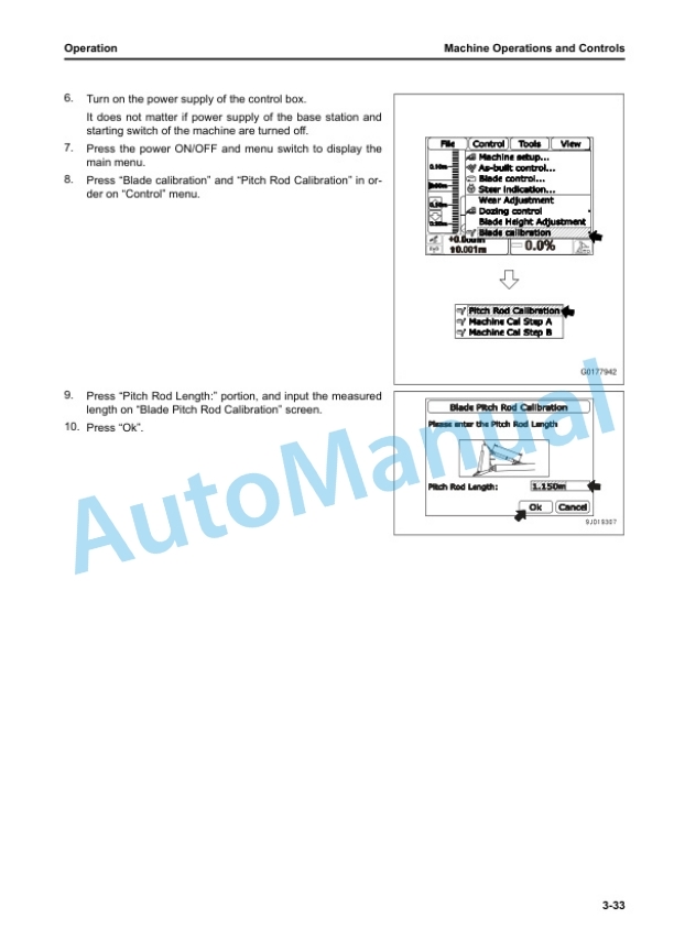
- 5.4.8. Calibrate Blade Position
- 5.5. Tools Menu
- 5.5.1. Radio Device Settings
- 5.5.2. Position Settings
- 5.5.2.1. How to Examine Blade Elevation
- 5.5.3. Navigate Points
- 5.5.3.1. How to Navigate to Points
- 5.5.4. Topo Shot for Topographic Survey
- 5.5.4.1. Do Topographic Surveys
- 5.5.5. Set Sitelink3D
- 5.5.5.1. Setting Contents by Sitelink3D Menu
- 5.5.6. Komatsu Options
- 5.5.6.1. How to Show Komatsu Options Screen
- 5.5.6.2. Komatsu Options Menu
- 5.5.7. Supervisor Mode
- 5.5.7.1. How to Use Supervisor Mode
- 5.5.7.2. How to Lock Menus, Buttons and Screen Items
- 5.5.7.3. How to Change Password
- 5.5.7.4. How to Finish Lock Mode
- 5.6. View Menu
- 5.6.1. Main Window Display
- 5.6.1.1. How to Show Main Window Display
- 5.6.2. Left Window Display
- 5.6.2.1. How to Show Left Window Display
- 5.6.3. Right Window Display
- 5.6.3.1. How to Show Right Window Display
- 5.6.4. Lower Window Display
- 5.6.4.1. How to Show Lower Window Display
- 5.6.5. Display Options
- 5.6.5.1. How to Show Display Options
- 5.6.5.2. How to Set Working Surface Display
- 5.6.5.3. How to Set Alignment Display
- 5.6.5.4. How to Set ASBUILT Surface Display
- 5.6.5.5. How to Set Point Display
- 5.6.5.6. How to Set Shortcuts Display
- 5.6.5.7. How to Set Background Color Display
- 5.6.5.8. How to Set Shown Units
- 5.6.5.9. How to Select Language
- 5.6.6.1. How to Show 3DMC Information
- 5.7. Main Window Display
- 5.7.1. Elevation Control Key
- 5.7.2. Slope Control Key
- 5.7.3. Shortcut on the Main Window
- 5.7.3.1. Toggle ASBUILT Mode
- 5.7.3.2. Start/Stop ASBUILT Updates
- 5.7.3.3. Dozing Mode Selection
- 5.7.3.4. Blade Load Selection
- 5.7.3.5. Get Topo Shot
- 5.7.3.6. Task Detail
- 5.7.3.7. Sitelink3D Messaging
- 5.7.3.8. Sitelink3D Work
- 5.7.3.9. Material Selection
- 5.7.4. Pan of Main Map View
- 5.8. Operation on Main Menu
- 5.8.1. How to Show GNSS Information
- 5.8.2. How to Adjust Cut/Fill Offsets
- 5.8.3. How to Change Grade Indicator Display
- 5.8.3.1. How to Change Slope Display
- 5.8.3.2. How to Change on Grade
- 5.8.3.3. How to Change Range
- 5.8.3.4. How to Change Highlight Color
- 5.8.4. How to Change Display of Light Bar
- 5.8.5. Operation by Popup Menu
- 5.8.5.1. Display Extended Status Text in Plan/Profile/Section
- 5.8.5.2. How to Adjust Cut/Fill Offsets (Popup Menu)
- 5.8.5.3. How to Navigate to Points (Popup Menu)
- 5.8.5.4. How to Use Polyline
- 5.8.5.5. Move the Steer Point (Pop Up Menu)
- 5.8.5.6. How to Set Isolate Surface Region
- 6. Specifications
- 6.1. Specifications
- 6.1.1. Specifications D155AXI8
- 7. INDEX










There are no reviews yet.