
Description
-
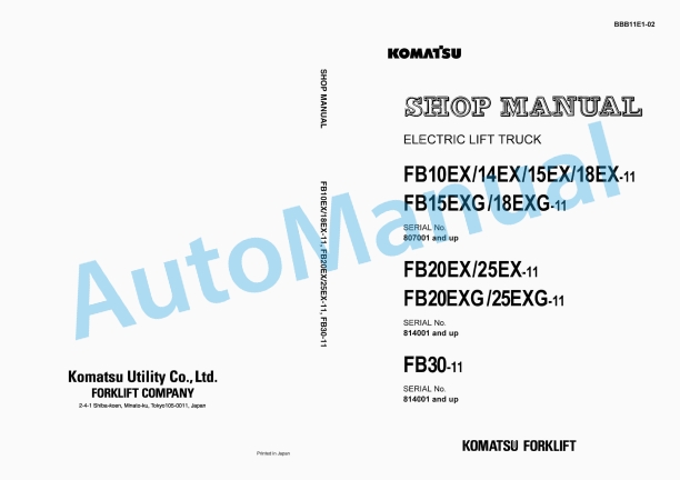
Model List:
- FB10EX-11 Electric Lift Truck
- FB14EX-11 Electric Lift Truck
- FB15EX-11 Electric Lift Truck
- FB18EX-11 Electric Lift Truck
- FB15EXG-11 Electric Lift Truck
- FB18EXG-11 Electric Lift Truck
- FB20EX-11 Electric Lift Truck
- FB25EX-11 Electric Lift Truck
- FB20EXG-11 Electric Lift Truck
- FB25EXG-11 Electric Lift Truck
- FB30-11 Electric Lift Truck
- 1. SECTION INDEX
- 1.1. Foreword
- 1.2. PRECAUTIONS WHEN PERFORMING THE SERVICE WORK
- 1.3. description of the symbols
- 2. GENERAL AND SPECIFICATIONS
- 2.1. Outside view and specifications
- 2.2. SAFETY ITEMS FOR MAINTENANCE
- 2.3. standard tightening torque for bolts
- 2.4. STANDARD TIGhTENING TORQUE FOR PIPE JOINTS
- 2.5. How to use LOCTITE
- 2.6. conversion table
- 2.7. PERIODIC REPLACEMENT OF CONSUMABLE PARTS
- 3. TESTING AND ADJUSTING
- 3.1. Service data (1.0 1.75 tON models)
- 3.2. Service data (2.0 3.0 tON models)
- 3.3. How to operate lift interrupt function
- 3.4. How to reset electrolyte level indicator function
- 3.5. How to start hour meter
- 3.6. Operation of meter panel
- 3.7. Adjusting lowering speed of fork
- 3.8. (PROPORTIONAL SOLENOID VALVE)
- 3.9. Battery
- 3.10. Fuse
- 3.11. Transfer case
- 3.12. Stationary charger
- 3.13. Brake pedal
- 3.14. Wheel brake
- 3.15. Adjusting parking brake lever
- 3.16. Hydraulic tank
- 3.17. Rear axle (Steering axle)
- 3.18. Mast (1.0 1.75 ton models)
- 3.19. Mast (2.0 3.0 ton models)
- 3.20. fork carriage (1.0 1.75 ton models)
- 3.21. fork carriage (2.0 3.0 ton models)
- 3.22. Measuring hydraulic drift of hydraulic cylinder and hydraulic drift of leaning forward
- 3.23. Bleeding air
- 4. Removal and installation
- 4.1. Arrangement of units
- 4.2. Weight of each unit (1.0 1.75 ton models)
- 4.3. Weight of each unit (2.0 3.0 ton models)
- 4.4. General disassembly and assembly drawing
- 4.5. Mast
- 4.6. Lift cylinder
- 4.7. Power train (Front axle Transfer Drive motor)
- 4.8. Rear axle
- 4.9. Battery
- 4.10. EPS actuator
- 4.11. Steering gear box
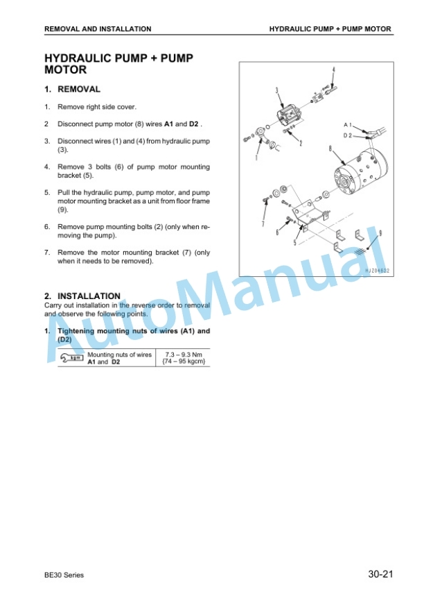
- 4.12. Hydraulic pump Pump motor
- 5. Disassembly and assembly
- 5.1. Transfer (1.0 1.75 ton models)
- 5.2. Transfer (2.0 2.5 ton models)
- 5.3. Transfer (3.0 ton model)
- 5.4. Differential (1.0 1.75 ton models)
- 5.5. Differential (2.0 3.0 ton models)
- 5.6. Front axle (1.0 1.75 ton models)
- 5.7. Front axle (2.0 2.5 ton models)
- 5.8. Front axle (3.0 ton model)
- 5.9. Brake master cylinder
- 5.10. Damping cylinder
- 5.11. Wheel brake (1.0 1.75 ton models)
- 5.12. Wheel brake (2.0 2.5 ton models)
- 5.13. Steering gear box
- 5.14. EPS actuator
- 5.15. Wheel brake (3.0 ton model)
- 5.16. Rear axle (1.0 1.75 ton models)
- 5.17. Rear axle (2.0 3.0 ton models)
- 5.18. Lift cylinder
- 5.19. tilt cylinder (6/12)
- 5.20. Hydraulic pump
- 5.21. Control valve (Proportional solenoid valve spec.)
- 5.22. Control valve (Manual valve spec.)
- 5.23. pump motor
- 5.24. Drive motor
- 6. MAINTENANCE STANDARD
- 6.1. Transfer
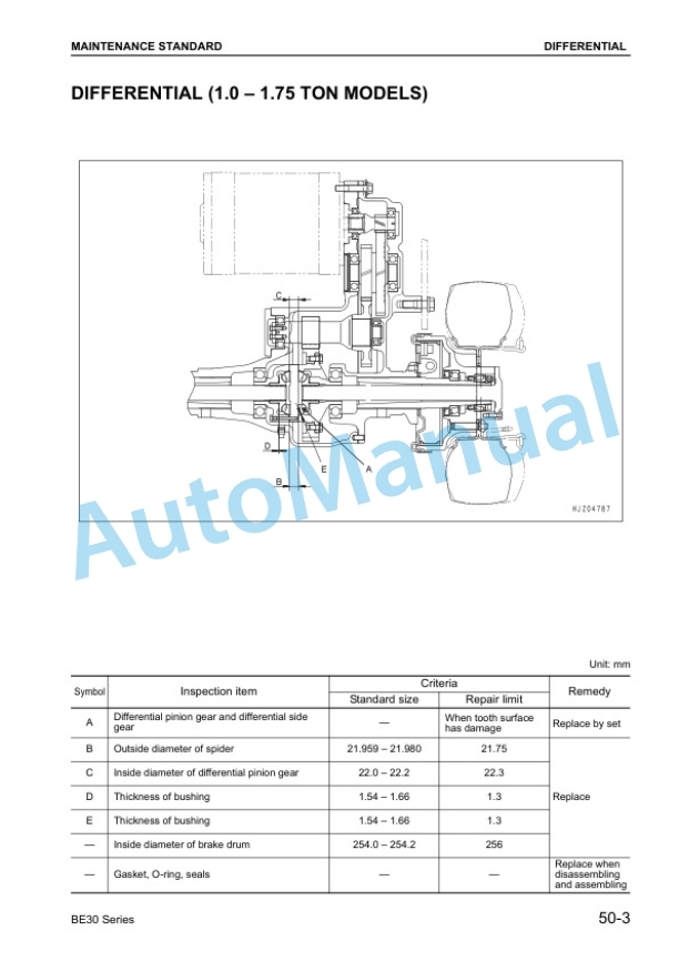
- 6.2. Differential (1.0 1.75 ton models)
- 6.3. Differential (2.0 3.0 ton models)
- 6.4. Front axle (1.0 1.75 ton models)
- 6.5. Front axle (2.0 2.5 ton models)
- 6.6. Front axle (3.0 ton model)
- 6.7. Brake master cylinder
- 6.8. Damping cylinder
- 6.9. Wheel brake (1.0 1.75 ton models)
- 6.10. Wheel brake (2.0 2.5 ton models)
- 6.11. Wheel brake (3.0 ton model)
- 6.12. Rear axle (1.0 1.75 ton models)
- 6.13. Rear axle (2.0 3.0 ton models)
- 6.14. Lift cylinder
- 6.15. Tilt cylinder
- 6.16. Control valve (Proportional solenoid valve spec.)
- 6.17. Control valve (Manual valve spec.)
- 6.18. Hydraulic pump
- 6.19. Mast, fork carriage, and fork (1.0 1.75 ton models)
- 6.20. Mast, fork carriage, and fork (2.0 3.0 ton models)
- 6.21. Drive motor (1.0 2.5 ton models)
- 6.22. Drive motor (3.0 ton model)
- 6.23. Pump motor (1.0 1.75 ton models)
- 6.24. Pump motor (2.0 3.0 ton models)
- 6.25. Power steering motor
- 7. Structure and function
- 7.1. Power train
- 7.2. Travel system
- 7.3. Braking device
- 7.4. Steering system
- 7.5. Hydraulic system
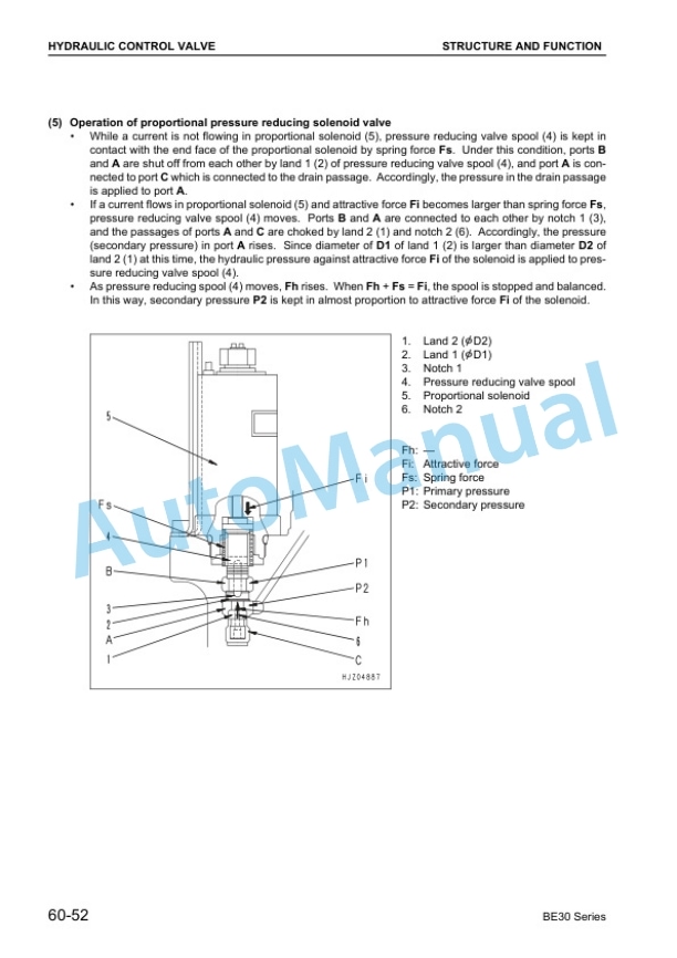
- 7.6. Hydraulic control valve (Proportional solenoid valve spec.)
- 7.7. Work equipment
- 7.8. Power connector for optional devices
- 7.9. Control unit
- 7.10. Operating device (Meter panel, switches, etc.)
- 8. TROUBLESHOOTING
- 8.1. Controller
- 8.2. Main controller
- 8.3. Drive motor
- 8.4. Electric circuit diagram (A3)
- 8.5. Electric circuit diagram (A3)
- 8.6. Electric circuit diagram (A3)
- 8.7. Electric circuit diagram (A3)
- 8.8. Electric circuit diagram (A3)
- 8.9. Sub controller
- 8.10. Troubleshooting
- 8.11. SELFDIAGNOSIS LOGIC TABLE (1.0 3.0 ton models)
- 8.12. CHARGER
- 9. Yearly inspection criteria
- 9.1. Starting motor and pump motor
- 9.2. Battery
- 9.3. Controller
- 9.4. Power train
- 9.5. Travel system
- 9.6. Steering system
- 9.7. Brake system
- 9.8. Cargo handling system



There are no reviews yet.