

Description
-
Model List:
- HM400-5E0 Articulated Dump Truck
- 1. Cover
- 2. Drawings of removed units (travel)
- 3. Dimensions of removed units (travel)
- 4. Drawings of removed units (non travel)
- 5. Dimensions of removed units (non travel)
- 6. Assembly procedure, necessary equipments, and schedule (travel)
- 7. Necessary tools and equipments (travel)
- 8. Assembly procedure, necessary equipments, and schedule (non travel)
- 9. Necessary tools and equipments (non travel)
- 10. Assembly procedure
- 10.1. No. 0100 Stationary bare machine (travel)
- 10.2. No. 0101 Stationary bare machine (nontravel) (without front and rear wheels, dump body)
- 10.3. No. 0170 Installation of tire and wheel assembly
- 10.4. No. 0200 Unfolding of rearview mirror (non travel)
- 10.5. No. 0310 Installation of KOMTRAX antenna
- 10.6. No. 0315 Installation of radio antenna
- 10.7. No. 0320 Installation of payload meter and yellow revolving lamp
- 10.8. No. 0325 Installation of payload meter
- 10.9. No. 0400 ADT assembly Bushing installation (optional)
- 10.10. No. 0410 ADT assembly Side arm installation (optional)
- 10.11. No. 0415 ADT assembly Assembling procedure of side arm mounting bolt
- 10.12. No. 0420 ADT assembly with tailgate (optional)
- 10.13. No. 0430 ADT assembly with tailgate (optional)
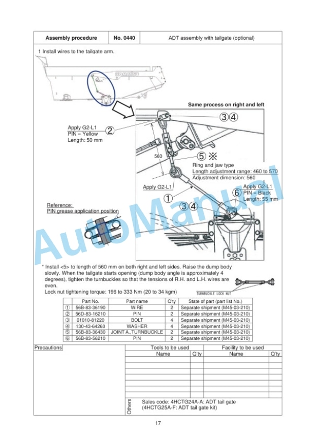
- 10.14. No. 0440 ADT assembly with tailgate (optional)
- 10.15. No. 0450 ADT assembly with tailgate (optional)
- 10.16. No.0460 ADT assembly Lubrication piping installation
- 10.17. No. 0530 Installation of R.H. fender mudguard
- 10.18. No. 0540 Installation of L.H. fender mudguard
- 10.19. No. 0600 Leveling procedure for machine rear section (packing style without dump body or with dump body packed separately)
- 10.20. No. 0610 Sling and put stationary dump body
- 10.21. No. 0620 Assembly of dump body subassembly
- 10.22. No. 0630 Installation of dump body
- 10.23. No. 0640 Connection of hoist cylinder
- 10.24. No. 0643 Installation of hoist pipe guard R.H.
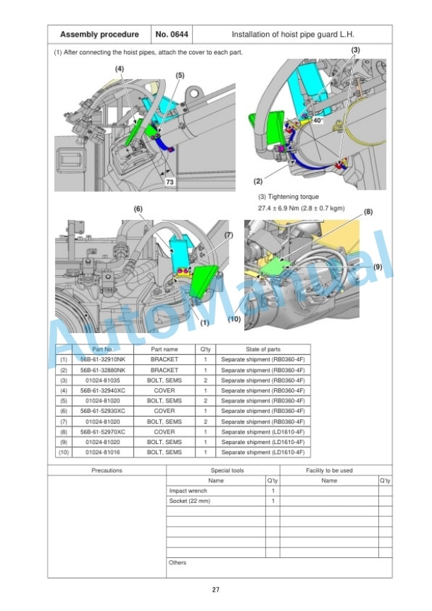
- 10.25. No. 0644 Installation of hoist pipe guard L.H.
- 10.26. No. 0650 Connection and adjustment of dump angle sensor
- 10.27. No. 0660 Installation and adjustment of dump body bottom mounting
- 10.28. No. 0670 Installation of dump body stopper
- 10.29. No. 0680 Installation of the blind bolt and washer after installing the dump body
- 10.30. No.0685 Dump body control calibration
- 10.31. No. 0690 Sticking of decal on dump body
- 10.32. No. 0695 Sticking of decal on dump body (optional)
- 10.33. No. 0696 Installation of tieoff bracket (packing style without dump body or with dump body packed separately)
- 10.34. No. 0697 Sticking of certificate decals (dump body) for KAL
- 10.35. No. 0700 Touch up painting of dump body
- 10.36. No. 0710 Adjustment1 of rearview monitor
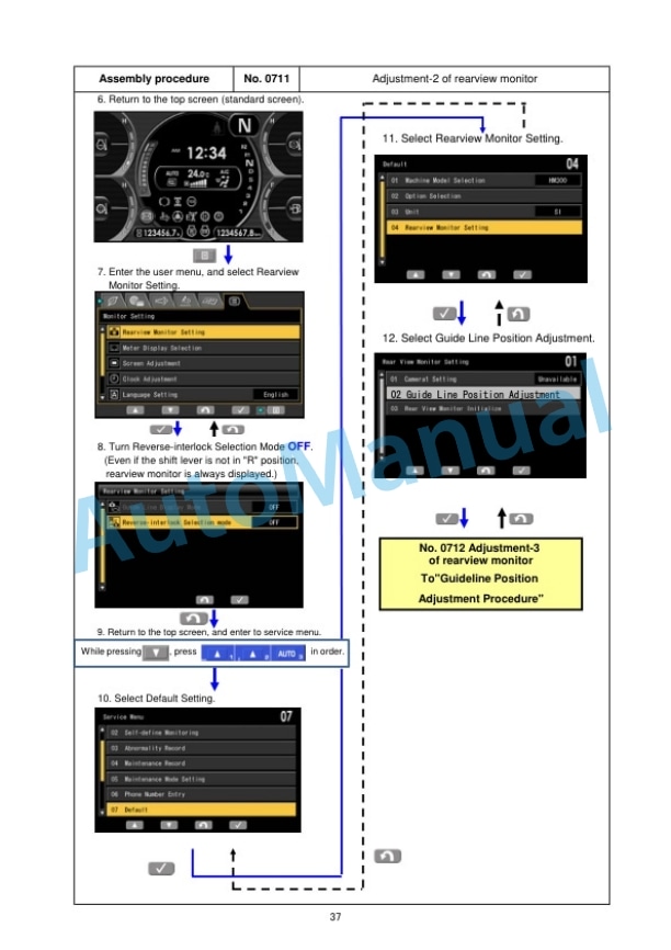
- 10.37. No. 0711 Adjustment2 of rearview monitor
- 10.38. No. 0712 Adjustment3 of rearview monitor
- 10.39. No. 0713 Adjustment4 of rearview monitor
- 10.40. No. 0800 Nitrogen gas adjustment of front and rear suspensions
- 10.41. No. 0810 Method for checking and inflating tire
- 11. Appendix
- 11.1. Adjustment of mirror
- 11.2. Machine check sheet for field assembly





There are no reviews yet.