

Description
-
Model List:
- PC20MR-2 Galeo Hydraulic Excavator
- PC27MR-2 Galeo Hydraulic Excavator
- PC30MR-2 Galeo Hydraulic Excavator
- 1. Contents
- 2. General
- 2.1. Specification dimension drawing
- 2.2. Working range drawing
- 2.3. Specifications
- 2.4. Weight table
- 2.5. Lubricants, fuel and coolant specifications
- 3. STRUCTURE, FUNCTION AND MAINTENANCE STANDARD
- 3.1. Swing machinery
- 3.2. Idler cushion
- 3.3. Idler
- 3.4. Hydraulic components layout drawing
- 3.5. Center swivel joint
- 3.6. Travel motor
- 3.7. Travel motor
- 3.8. Hydraulic cylinder
- 3.9. Operation for each function and valve
- 3.10. Swing motor
- 3.11. Swing motor
- 3.12. Ppc valve
- 3.13. Work equipment
- 3.14. Dimensions of each part of work equipment
- 3.15. Floor
- 3.16. Engine control
- 3.17. Electric control system
- 3.18. Component parts of system
- 3.19. Monitor system
- 3.20. Monitor panel
- 3.21. Sensors
- 4. TESTING AND ADJUSTING
- 4.1. Standard value table for engine related parts
- 4.2. Standard value table for chassis related parts
- 4.3. Testing and adjusting
- 4.3.1. List of testing, adjusting, and troubleshooting tools
- 4.3.2. Measuring engine speed
- 4.3.3. Measurement of exhaust gas color
- 4.3.4. Adjusting valve clearance
- 4.3.5. Adjusting valve clearance
- 4.3.6. Measuring compression pressure
- 4.3.7. Measuring compression pressure
- 4.3.8. Measuring engine oil pressure
- 4.3.9. Testing and adjusting fuel injection timing
- 4.3.10. Testing and adjusting fuel injection timing
- 4.3.11. Bleeding air from fuel circuit
- 4.3.12. Testing and adjusting alternator belt tension
- 4.3.13. Testing and adjusting alternator belt tension
- 4.3.14. Adjusting fuel control lever linkage
- 4.3.15. Measurement of clearance in swing circle bearings
- 4.3.16. Testing wear of sprocket
- 4.3.17. Testing and adjusting track shoe tension
- 4.3.18. Testing and adjusting oil pressures in work equipment, travel, swing, and blade circuits
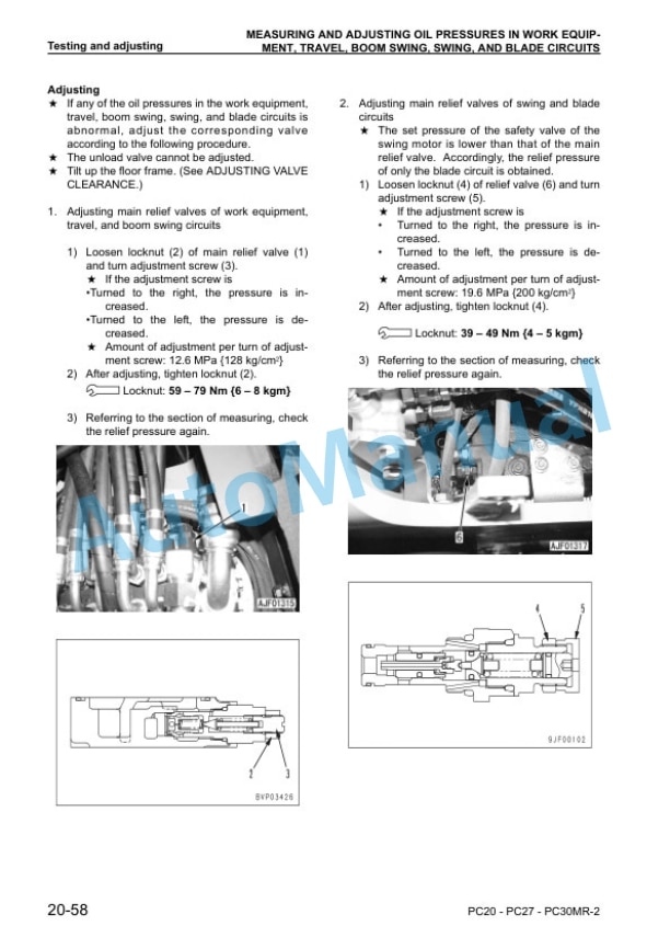
- 4.3.19. Measuring and adjusting oil pressures in work equipment, travel, boom swing, swing, and blade circuits
- 4.3.20. Measuring control circuit basic pressure
- 4.3.21. Testing and adjusting pump ls differential pressure
- 4.3.22. Measuring and adjusting ls differential pressure
- 4.3.23. Measuring solenoid valve output pressure
- 4.3.24. Measuring ppc valve output pressure
- 4.3.25. Adjusting play of work equipment and swing ppc valves
- 4.3.26. Measuring swing holding brake release pressure
- 4.3.27. Measuring swing holding brake release pressure
- 4.3.28. Testing and adjusting travel deviation
- 4.3.29. Measurement of oil leakage from cylinder
- 4.3.30. Releasing residual pressure from hydraulic circuit
- 4.3.31. Bleeding air from cylinder
- 4.3.32. Pressurizing hydraulic tank
- 4.3.33. Bleeding air from each part
- 4.3.34. How to open and close (tilt) floor
- 4.3.35. Inspection procedures for diode
- 4.3.36. Troubleshooting
- 4.4. Troubleshooting of electrical system PC20MR2 (Except monitor panel) (E mode)
- 4.4.1. Before starting emode troubleshooting
- 4.4.2. Information contained in troubleshooting table
- 4.5. Troubleshooting of electrical system PC27MR2 PC30MR2 (Except monitor panel) (E mode)
- 4.5.1. Before starting emode troubleshooting
- 4.5.2. Information contained in troubleshooting table
- 4.6. Troubleshooting of hydraulic and mechanical system (PC20MR2) (H mode)
- 4.6.1. INFORMATION CONTAINED IN TROUBLESHOOTING TABLE
- 4.7. Troubleshooting of hydraulic and mechanical system (PC27MR2 PC30MR2) (H mode)
- 4.7.1. Information contained in troubleshooting table
- 4.8. Troubleshooting of monitor panel system (PC20MR2) (M mode)
- 4.8.1. Before starting Mmode troubleshooting
- 4.8.2. Information contained in troubleshooting table
- 4.9. Troubleshooting of monitor panel (PC2730MR2) system (Mmode)
- 4.9.1. Before starting Mmode troubleshooting
- 4.9.2. Information contained in troubleshooting table
- 4.10. TROUBLESHOOTING OF ENGINE (PC20MR2) (SMODE)
- 4.10.1. Troubleshooting of engine (smode)
- 4.11. TROUBLESHOOTING OF ENGINE (PC2730MR2) (SMODE)
- 4.11.1. Method of using troubleshooting charts
- 5. Disassembly and assembly
- 5.1. How to read this manual
- 5.2. Precautions when performing operation
- 5.3. Special tool list
- 5.4. Removal and installation of fuel injection pump assembly
- 5.5. Removal and installation of fuel injection pump assembly
- 5.6. Removal and installation of radiator and hydraulic oil cooler assembly
- 5.7. Removal and installation of radiator and hydraulic oil cooler assembly
- 5.8. Removal and installation of engine and hydraulic pump assembly
- 5.9. Removal and installation of engine and hydraulic pump assembly
- 5.10. Removal and installation of track shoe assembly
- 5.11. Disassembly and assembly of idler assembly
- 5.12. Disassembly and assembly of recoil spring assembly
- 5.13. Disassembly and assembly of carrier roller assembly
- 5.14. Disassembly and assembly of track roller assembly
- 5.15. Removal and installation of center swivel joint assembly
- 5.16. Removal and installation of center swivel joint assembly
- 5.17. Disassembly and assembly of center swivel joint assembly
- 5.18. Removal and installation of floor frame assembly
- 5.19. Removal and installation of floor frame assembly
- 5.20. Removal and installation of swing motor and swing machinery assembly
- 5.21. Removal and installation of swing motor and swing machinery assembly
- 5.22. Disassembly and assembly of swing motor and swing machinery assembly
- 5.23. Removal and installation of work equipment assembly
- 5.24. Removal and installation of revolving frame assembly
- 5.25. Removal and installation of revolving frame assembly
- 5.26. Removal and installation of swing circle assembly
- 5.27. Disassembly and assembly of control valve assembly
- 5.28. Disassembly and assembly of hydraulic cylinder assembly
- 5.29. Disassembly and assembly of hydraulic cylinder assembly
- 5.30. Removal and installation of air conditioner unit assembly
- 5.31. Removal and installation of front window assembly
- 5.32. Removal and installation of operators cab glass (stuck glass)
- 6. OTHERS
- 6.1. Hydraulic circuit diagram (PC20MR2)
- 6.2. Hydraulic circuit diagram (PC27MR2)
- 6.3. Hydraulic circuit diagram (PC30MR2)
- 6.4. Electrical circuit diagram (PC20MR2)
- 6.5. Electrical circuit diagram (PC2730MR2)











There are no reviews yet.