
Description
-
Model List:
- PC750-7 Hydraulic Excavator
- PC750LC-7 Hydraulic Excavator
- PC750SE-7 Hydraulic Excavator
- PC800-7 Hydraulic Excavator
- PC800SE-7 Hydraulic Excavator
- 1. COVER
- 2. Foreword
- 3. CONTENTS
- 4. SPECIFICATIONS
- 5. Precautions for field assembly
- 6. DISPOSAL OF REMOVED PARTS
- 7. Assembling Procedures, Applicable Equipment and Schedule
- 8. TRANSPORTATION
- 9. List of Tools for Field Assembling
- 10. TIGHTENING TORQUE
- 11. COATING MATERIALS LIST
- 12. ASSEMBLY OF CHASSIS
- 12.1. A1. Installation of Left and Right Track Frames
- 12.2. A2. Installation of Travel Pipe
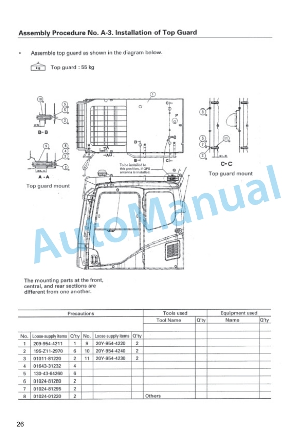
- 12.3. A3. Installation of Top Guard
- 12.4. A4. Installation of Radiator Cover
- 12.5. A5. Installation of Rearview Mirror
- 12.6. A6. Installation of Handrail
- 12.7. A7. Installation of Step
- 12.8. A8. Installation of Left Side Step
- 12.9. A9. Installation of Muffler Tail Tube
- 12.10. A10. Sticking of Sheet (to Counterweight)
- 12.11. A11. Installation of Counterweight
- 12.12. A12. Installation of ORBCOMM Antenna (if equipped)
- 12.13. A13. Installation of Step Light
- 12.14. A14. Installation of Travel Pipe Cover
- 12.15. A15. Extension of Track Frame Gauge (Only When 3split Packages are transported)
- 12.16. A16. Testing Track Shoe Tension
- 12.17. A17. Installation of Oil Amount and Water Amount
- 12.18. A18. Parts to be Touched up After Field Assembly
- 13. ASSEMBLING OF WORK EQUIPMENT OF BACKHOE
- 13.1. B1. Pulling Out of Boom Foot Pin, and Boom Cylinder Foot Pin
- 13.2. B2. Installation of Boom Assembly
- 13.3. B3. Relieving Remaining Pressure from Hydraulic Circuit
- 13.4. B4. B2. Installation of Boom Cylinder Foot
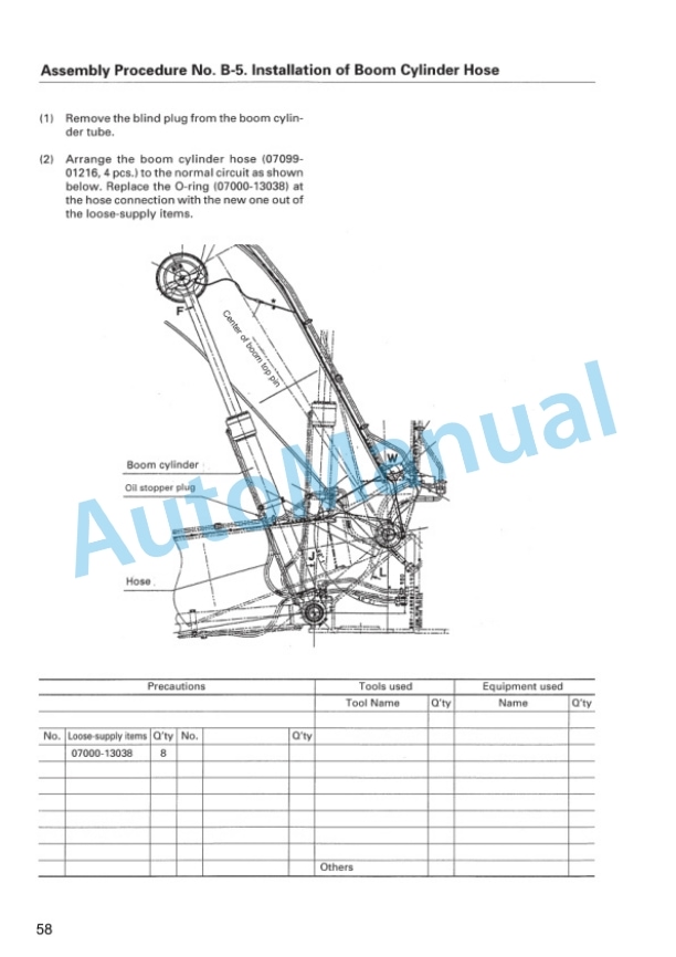
- 13.5. B5. Installation of Boom Cylinder Hose
- 13.6. B6. Installation of Boom Cylinder
- 13.7. B7. Installation of Arm Cylinder
- 13.8. B8. Installation of Arm Cylinder Hose
- 13.9. B9. Installation of Arm Assembly
- 13.10. B10. Installation of Hose between Boom and Bucket Cylinder
- 13.11. B11. Installation of Bucket Assembly
- 13.12. B12. Lubrication Piping to Work Equipment
- 13.13. B13. Connection of Wiring of Work Equipment
- 13.14. B14. Greasing after Assembling Work Equipment
- 13.15. B15. Air Bleeding from Hydraulic Cylinder
- 14. ASSEMBLING OF WORK EQUIPMENT OF LOADING SHOVEL
- 14.1. C1. Releasing residual pressure in hydraulic circuit
- 14.2. C2. Pulling out boom foot pin and boom cylinder foot pin
- 14.3. C3. Installation of boom and arm assembly
- 14.4. C4. Installation of flushing piping between chassis and boom
- 14.5. C5. Installation of flushing piping for boom cylinder and arm cylinder
- 14.6. C6. Installation offlushing piping for bucket cylinder
- 14.7. C7. Installation of flushing piping for bottom dump cylinder
- 14.8. C8. Installation of boom cylinder
- 14.9. C9. Installation of boom cylinder foot
- 14.10. C10. Installation of boom cylinder hoses
- 14.11. C11. Installation of boom cylinder rod pin
- 14.12. C12. Installation of arm cylinder hoses
- 14.13. C13. Installation of bucket cylinder
- 14.14. C14. Installation of bucket cylinder hose
- 14.15. C15. Installation of connecting hoses between chassis and boom top
- 14.16. C16. Installation of bottom dump cylinder hoses
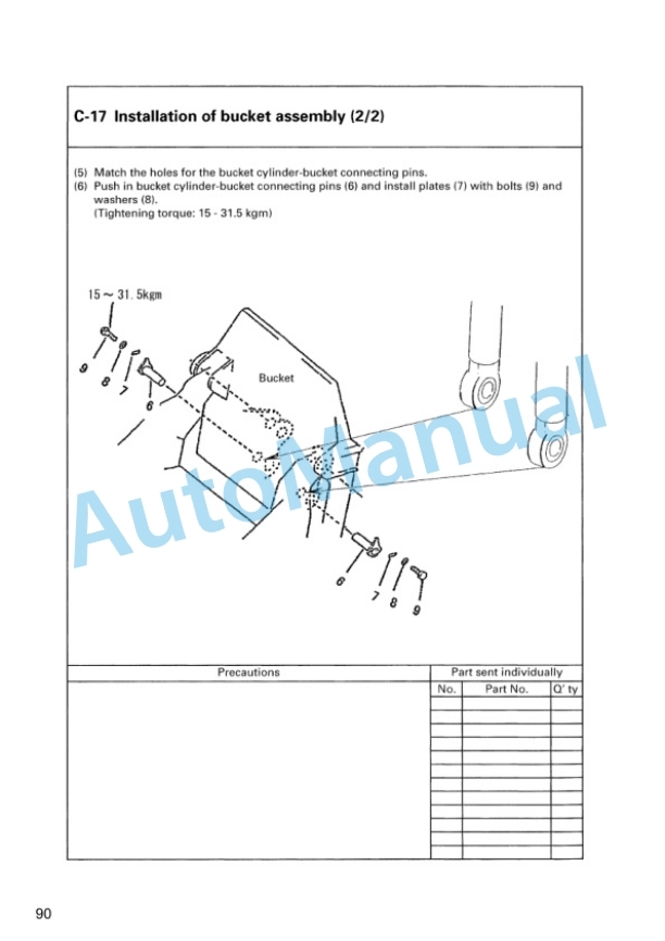
- 14.17. C17. Installation of bucket assembly
- 14.18. C18. Installation of working lamps
- 14.19. C19. Installation of work equipment grease piping
- 14.20. C20. Greasing after assembling of work equipment
- 14.21. C21 Bleeding air from hydraulic cylinder
- 15. PROCEDURE FOR INSPECTION AND MAINTENANCE AFTER COMPLETION OF ASSEMBLY
- 15.1. M1.Inspection of Oil Level in Hydraulic Tank and Refill
- 15.2. M2.Replacement of Return Filter (Standard Filter to Flushing Filter)
- 15.3. M3.Flushing of Hydraulic Circuit
- 15.4. M4.Replacement of Return Filter (Flushing Filter to Standard Filter)
- 16. FIELD ASSEMBLY INSPECTION REPORT (Backhoe)
- 17. FIELD ASSEMBLY INSPECTION REPORT (Loading Shovel)





There are no reviews yet.