
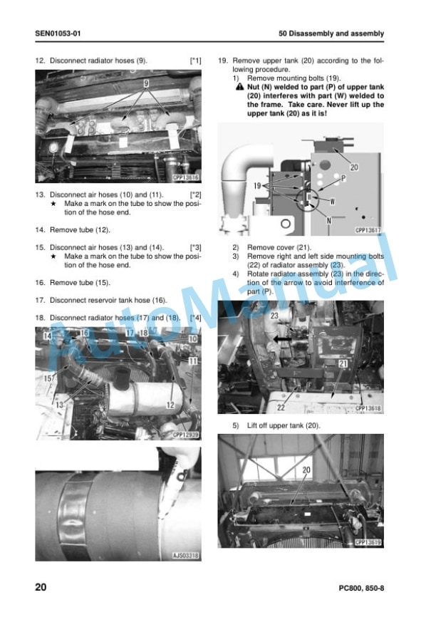
Description
-
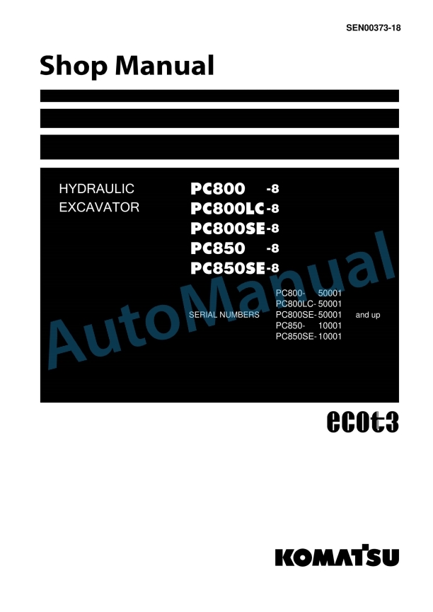
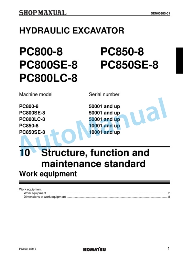
Model List:
- PC800-8 Hydraulic Excavator
- PC800LC-8 Hydraulic Excavator
- PC800SE-8 Hydraulic Excavator
- PC850-8 Hydraulic Excavator
- PC850SE-8 Hydraulic Excavator
- 1. Cover
- 2. Index and foreword
- 2.1. Index
- 2.1.1. Composition of shop manual
- 2.1.2. Table of contents
- 2.2. Foreword and general information
- 2.2.1. Safety notice
- 2.2.2. How to read the shop manual
- 2.2.3. Explanation of terms for maintenance standard
- 2.2.4. Handling of electric equipment and hydraulic component
- 2.2.5. Handling of connectors newly used for engines
- 2.2.6. How to read electric wire code
- 2.2.7. Precautions when carrying out operation
- 2.2.8. Method of disassembling and connecting pushpull type coupler
- 2.2.9. Standard tightening torque table
- 2.2.10. Conversion table
- 3. Specification
- 3.1. Specification and technical data
- 3.1.1. Specification and technical data
- 4. Structure, function and maintenance standard
- 4.1. Engine and cooling system
- 4.1.1. Engine and cooling system
- 4.2. Power train
- 4.2.1. Power train
- 4.3. Undercarriage and frame
- 4.3.1. Undercarriage and frame
- 4.4. Hydraulic system, Part 1
- 4.4.1. Hydraulic system, Part 1
- 4.5. Hydraulic system, Part 2
- 4.5.1. Hydraulic system, Part 2
- 4.6. Work equipment
- 4.6.1. Work equipment
- 4.7. Cab and its attachments
- 4.7.1. Cab and its attachments
- 4.8. Electrical system
- 4.8.1. Engine control
- 4.8.2. Electric control system
- 4.8.3. Monitor system
- 4.8.4. Sensors
- 4.8.5. KOMTRAX system
- 5. Standard value table
- 5.1. Standard service value table
- 5.1.1. Standard service value table
- 6. Testing and adjusting
- 6.1. Testing and adjusting, Part 1
- 6.1.1. Testing and adjusting, Part 1
- 6.2. Testing and adjusting, Part 2
- 6.2.1. Testing and adjusting, Part 2
- 6.3. Testing and adjusting, Part 3
- 6.3.1. Testing and adjusting, Part 3
- 6.4. Testing and adjusting, Part 4
- 6.4.1. Testing and adjusting, Part 4
- 6.5. Testing and adjusting, Part 5
- 6.5.1. Testing and adjusting, Part 5
- 7. Troubleshooting
- 7.1. Failure code table and fuse locations
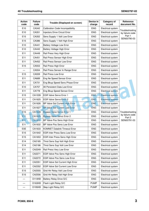
- 7.1.1. Failure code table and fuse locations
- 7.2. General information on troubleshooting
- 7.2.1. General information on troubleshooting
- 7.3. Troubleshooting by failure code (Display of code), Part 1
- 7.3.1. Troubleshooting by failure code (Display of code), Part 1
- 7.4. Troubleshooting by failure code (Display of code), Part 2
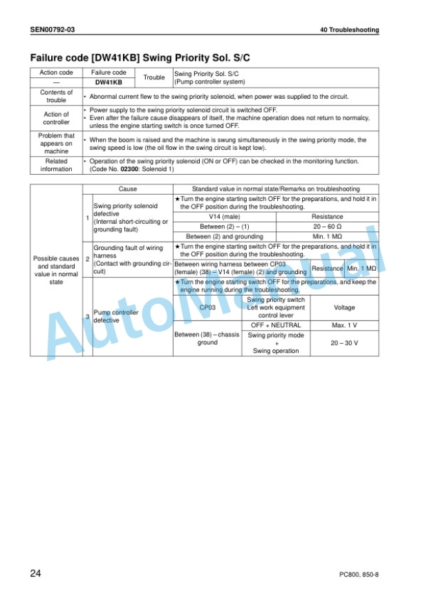
- 7.4.1. Troubleshooting by failure code (Display of code), Part 2
- 7.5. Troubleshooting by failure code (Display of code), Part 3
- 7.5.1. Troubleshooting by failure code (Display of code), Part 3
- 7.6. Troubleshooting of electrical system (Emode)
- 7.6.1. Troubleshooting of electrical system (Emode)
- 7.7. Troubleshooting of hydraulic and mechanical system (Hmode)
- 7.7.1. Troubleshooting of hydraulic and mechanical system (Hmode)
- 7.8. Troubleshooting of engine (Smode)
- 7.8.1. Troubleshooting of engine (Smode)
- 8. Disassembly and assembly
- 8.1. General information on disassembly and assembly
- 8.1.1. How to read this manual
- 8.1.2. Coating materials list
- 8.1.3. Special tools list
- 8.1.4. Sketches of special tools
- 8.2. Engine and cooling system (SAA6D140E5)
- 8.2.1. Engine and cooling system
- 8.3. Engine (SAA6D140E5)
- 8.3.1. Engine (SAA6D140E5)
- 8.4. Power train
- 8.4.1. Power train
- 8.5. Undercarriage and frame
- 8.5.1. Undercarriage and frame
- 8.6. Hydraulic system
- 8.6.1. Removal and installation ofhydraulic tank assembly
- 8.6.2. Removal and installation of mainpump assembly
- 8.6.3. Removal and installation of mainpump input shaft oil seal
- 8.6.4. Removal and installation ofcooling fan pump assembly
- 8.6.5. Removal and installation ofcontrol valve assembly
- 8.6.6. Assembly of control valveassembly
- 8.6.7. Removal and installation of swingmotor assembly
- 8.6.8. Removal and installation of centerswivel joint assembly
- 8.6.9. Disassembly and assembly ofcenter swivel joint assembly
- 8.6.10. Removal and installation of travelmotor assembly
- 8.6.11. Removal and installation of solenoidvalve assembly
- 8.6.12. Removal and installation of boomdamping valve assembly
- 8.6.13. Disassembly and assembly ofwork equipment PPC valveassembly
- 8.6.14. Disassembly and assembly oftravel PPC valve assembly
- 8.6.15. Disassembly and assembly ofhydraulic cylinder assembly
- 8.6.16. Disassembly and assembly ofgrease gun assembly
- 8.7. Work equipment
- 8.7.1. Work equipment
- 8.8. Cab and its attachments
- 8.8.1. Cab and its attachments
- 8.9. Electrical system
- 8.9.1. Electrical system
- 9. Diagrams and drawings
- 9.1. Hydraulic diagrams and drawings
- 9.1.1. Hydraulic circuit diagram
- 9.2. Electrical diagrams and drawings
- 9.2.1. Electrical circuit diagram (1/5)
- 9.2.2. Electrical circuit diagram (2/5)
- 9.2.3. Electrical circuit diagram (3/5)
- 9.2.4. Electrical circuit diagram (4/5)
- 9.2.5. Electrical circuit diagram (5/5)
- 9.2.6. Connector list and sterogram




There are no reviews yet.