
Description
-
Model List:
- PW170ES-6K Hydraulic Excavator
- 1. PW170ES 6K
- 2. K32001 and up K34001 and up
- 3. CONTENTS
- 4. GENERAL…………………………………………………HelveticaBold
- 5. STRUCTURE AND FUNCTION
- 6. TESTING AND ADJUSTING
- 7. DISASSEMBLY AND ASSEMBLY
- 8. MAINTENANCE STANDARD…………………………………………..
- 9. SAFETY
- 10. FOREWORD
- 11. HOW TO READ THE SHOP MANUAL
- 12. HOISTING INSTRUCTIONS
- 13. COATING MATERIALS
- 14. STANDARD TIGHTENING TORQUE
- 15. ELECTRIC WIRE CODE
- 16. CONVERSION TABLE
- 17. ENGINE RELATED PARTS
- 18. RADIATOR OIL COOLER
- 19. SWING CIRCLE
- 20. SWING MACHINERY UNDERCARRIAGE
- 21. CLUTCH CONTROL CIRCUIT
- 22. AXLE
- 23. SUSPENSION LOCK CYLINDER
- 24. BRAKING TRAIN
- 25. BRAKE PEDAL
- 26. BRAKE PEDAL INCORPORATING BRAKE VALVE
- 27. ACCUMULATOR FOR BRAKE SYSTEM
- 28. STEERING TRAIN
- 29. ITEM
- 30. STEERING COLUMN
- 31. HYDRAULIC CIRCUIT DIAGRAM
- 32. HYDRAULIC CIRCUIT DIAGRAM
- 33. HYDRAULIC TANK
- 34. HYDRAULIC TANK
- 35. HYDRAULIC PUMP
- 36. PPC PUMPLESS SYSTEM
- 37. CONTROL VALVE
- 38. CLSS
- 39. POINTS TO REMEMBER WHEN TROUBLESHOOTING
- 40. SEQUENCE OF EVENTS IN TROUBLESHOOTING
- 41. PRECAUTIONS WHEN CARRYING OUT MAINTENANCE
- 42. CHECKS BEFORE TROUBLESHOOTING
- 43. CONNECTOR TYPES
- 44. CONNECTION TABLE FOR CONNECTOR PIN NUMBERS
- 45. EXPLANATION OF CONTROL MACHANISM FOR ELECTRICAL SYSTEM
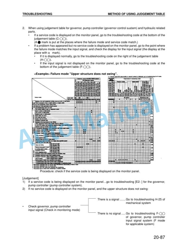
- 46. METHOD OF USING JUDGEMENT TABLE
- 47. METHOD OF USING TROUBLESHOOTING CHARTS
- 48. DETAILS OF TROUBLESHOOTING AND TROUBLESHOOTING PROCEDURE
- 49. SERVICE CODE TABLE
- 50. POINTS TO REMEMBER WHEN CARRYING OUT TROUBLESHOOTING OF GOVERNOR, PUMP CONTROLLER SYSTEM
- 51. ACTION TAKEN BY CONTROLLER WHEN ABNORMALITY OCCURS AND PROBLEMS ON MACHINE
- 52. JUDGEMENT TABLE FOR GOVERNOR, PUMP GOVERNOR ( GOVERNOR CONTROL SYSTEM) AND ENGINE RELATED PARTS
- 53. ELECTRICAL CIRCUIT DIAGRAM FOR E MODE 1/ 2
- 54. ELECTRICAL CIRCUIT DIAGRAM FOR E MODE 2/ 2
- 55. E 1 Abnormality in governor, pump controller power source ( controller LED is OFF)
- 56. E 2 E308 Abnormality in fuel control dial input value is displayed
- 57. E 3 E317 Abnormality ( disconnection) in motor drive system is displayed
- 58. E 4 E318 Abnormality ( short circuit) in motor drive system is displayed
- 59. E 5 E306 Abnormality in feedback potentiometer system is displayed
- 60. E 6 E315 Abnormality ( short circuit) in battery relay output system is displayed
- 61. E 7 E316 Abnormality ( step out) in motor is displayed
- 62. E 8 Engine does not start
- 63. METHOD OF USING TROUBLESHOOTING CHARTS
- 64. S 1 Starting performance is poor ( starting always takes time)
- 65. S 2 Engine does not start
- 66. S 3 Engine does not pick up smoothly ( follow up is poor)
- 67. S 4 Engine stops during operations
- 68. S 5 Engine does not rotate smoothly ( hunting)
- 69. S 6 Engine lacks output ( no power)
- 70. S 7 Exhaust smoke is black ( incomplete combustion)
- 71. S 8 Oil consumption is excessive ( or exhaust smoke is blue)
- 72. S 9 Oil becomes contaminated quickly
- 73. S 10 Fuel consumption is excessive
- 74. S 11 Oil is in cooling water, or water spurts back, or water level goes down
- 75. S 12 Oil pressure caution lamp lights up ( drop in oil pressure)
- 76. S 13 Oil level rises ( water, fuel in oil)
- 77. S 14 Water temperature becomes too high ( overheating)
- 78. S 15 Abnormal noise is made
- 79. S 16 Vibration is excessive
- 80. ELECTRICAL CIRCUIT DIAGRAM FOR C MODE 1/ 2 ELECTRICAL CIRCUIT DIAGRAM FOR C MODE 2/ 2 ELECTRICAL CIRCUIT DIAGRAM FOR F MODE 1/ 2 ELECTRICAL CIRCUIT DIAGRAM FOR F MODE 2/ 2
- 81. PW170ES 6K Serial number K32001 and up PW170ES 6K Serial number K32001 and up INSTALLATION OF OPERATORS CAB ASSEMBLY
- 82. REMOVAL OF COUNTERWEIGHT ASSEMBLY
- 83. INSTALLATION OF COUNTERWEIGHT ASSEMBLY
- 84. PW170ES 6K
- 85. K32001 and up K34001 and up
- 86. CONTENTS
- 87. GENERAL…………………………………………………HelveticaBold
- 88. STRUCTURE AND FUNCTION
- 89. TESTING AND ADJUSTING
- 90. DISASSEMBLY AND ASSEMBLY
- 91. MAINTENANCE STANDARD…………………………………………..
- 92. SAFETY
- 93. FOREWORD
- 94. HOW TO READ THE SHOP MANUAL
- 95. HOISTING INSTRUCTIONS
- 96. COATING MATERIALS
- 97. STANDARD TIGHTENING TORQUE
- 98. ELECTRIC WIRE CODE
- 99. CONVERSION TABLE
- 100. ENGINE RELATED PARTS
- 101. RADIATOR OIL COOLER
- 102. SWING CIRCLE
- 103. SWING MACHINERY UNDERCARRIAGE
- 104. CLUTCH CONTROL CIRCUIT
- 105. AXLE
- 106. SUSPENSION LOCK CYLINDER
- 107. BRAKING TRAIN
- 108. BRAKE PEDAL
- 109. BRAKE PEDAL INCORPORATING BRAKE VALVE
- 110. ACCUMULATOR FOR BRAKE SYSTEM
- 111. STEERING TRAIN
- 112. ITEM
- 113. STEERING COLUMN
- 114. HYDRAULIC CIRCUIT DIAGRAM
- 115. HYDRAULIC CIRCUIT DIAGRAM
- 116. HYDRAULIC TANK
- 117. HYDRAULIC TANK
- 118. HYDRAULIC PUMP
- 119. PPC PUMPLESS SYSTEM
- 120. CONTROL VALVE
- 121. CLSS
- 122. POINTS TO REMEMBER WHEN TROUBLESHOOTING
- 123. SEQUENCE OF EVENTS IN TROUBLESHOOTING
- 124. PRECAUTIONS WHEN CARRYING OUT MAINTENANCE
- 125. CHECKS BEFORE TROUBLESHOOTING
- 126. CONNECTOR TYPES
- 127. CONNECTION TABLE FOR CONNECTOR PIN NUMBERS
- 128. EXPLANATION OF CONTROL MACHANISM FOR ELECTRICAL SYSTEM
- 129. METHOD OF USING JUDGEMENT TABLE
- 130. METHOD OF USING TROUBLESHOOTING CHARTS
- 131. DETAILS OF TROUBLESHOOTING AND TROUBLESHOOTING PROCEDURE
- 132. SERVICE CODE TABLE
- 133. POINTS TO REMEMBER WHEN CARRYING OUT TROUBLESHOOTING OF GOVERNOR, PUMP CONTROLLER SYSTEM
- 134. ACTION TAKEN BY CONTROLLER WHEN ABNORMALITY OCCURS AND PROBLEMS ON MACHINE
- 135. JUDGEMENT TABLE FOR GOVERNOR, PUMP GOVERNOR ( GOVERNOR CONTROL SYSTEM) AND ENGINE RELATED PARTS
- 136. ELECTRICAL CIRCUIT DIAGRAM FOR E MODE 1/ 2
- 137. ELECTRICAL CIRCUIT DIAGRAM FOR E MODE 2/ 2
- 138. E 1 Abnormality in governor, pump controller power source ( controller LED is OFF)
- 139. E 2 E308 Abnormality in fuel control dial input value is displayed
- 140. E 3 E317 Abnormality ( disconnection) in motor drive system is displayed
- 141. E 4 E318 Abnormality ( short circuit) in motor drive system is displayed
- 142. E 5 E306 Abnormality in feedback potentiometer system is displayed
- 143. E 6 E315 Abnormality ( short circuit) in battery relay output system is displayed
- 144. E 7 E316 Abnormality ( step out) in motor is displayed
- 145. E 8 Engine does not start
- 146. METHOD OF USING TROUBLESHOOTING CHARTS
- 147. S 1 Starting performance is poor ( starting always takes time)
- 148. S 2 Engine does not start
- 149. S 3 Engine does not pick up smoothly ( follow up is poor)
- 150. S 4 Engine stops during operations
- 151. S 5 Engine does not rotate smoothly ( hunting)
- 152. S 6 Engine lacks output ( no power)
- 153. S 7 Exhaust smoke is black ( incomplete combustion)
- 154. S 8 Oil consumption is excessive ( or exhaust smoke is blue)
- 155. S 9 Oil becomes contaminated quickly
- 156. S 10 Fuel consumption is excessive
- 157. S 11 Oil is in cooling water, or water spurts back, or water level goes down
- 158. S 12 Oil pressure caution lamp lights up ( drop in oil pressure)
- 159. S 13 Oil level rises ( water, fuel in oil)
- 160. S 14 Water temperature becomes too high ( overheating)
- 161. S 15 Abnormal noise is made
- 162. S 16 Vibration is excessive
- 163. ELECTRICAL CIRCUIT DIAGRAM FOR C MODE 1/ 2 ELECTRICAL CIRCUIT DIAGRAM FOR C MODE 2/ 2 ELECTRICAL CIRCUIT DIAGRAM FOR F MODE 1/ 2 ELECTRICAL CIRCUIT DIAGRAM FOR F MODE 2/ 2
- 164. PW170ES 6K Serial number K32001 and up PW170ES 6K Serial number K32001 and up INSTALLATION OF OPERATORS CAB ASSEMBLY
- 165. REMOVAL OF COUNTERWEIGHT ASSEMBLY
- 166. INSTALLATION OF COUNTERWEIGHT ASSEMBLY
- 167. REMOVAL OF GOVERNOR PUMP CONTROLLER ASSEMBLY
- 168. INSTALLATION OF GOVERNOR, PUMP CONTROLLER ASSEMBLY
- 169. REMOVAL OF MONITOR PANEL ASSEMBLY
- 170. INSTALLATION OF MONITOR PANEL ASSEMBLY
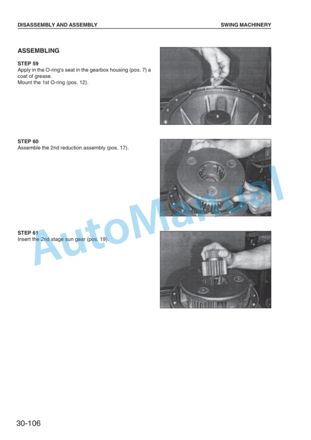
- 171. DISASSEMBLY OF SWING MACHINERY ASSEMBLY ( SPECIAL TOOLS FOR SWING MACHINERY) ( SPECIAL TOOLS FOR SWING MACHINERY) TRANSMISSION
- 172. FRONT AXLE
- 173. REAR AXLE
- 174. ADAPTER WELDING INSTRUCTION ELECTRODE WELDING
- 175. OUTRIGGER CYLINDER
- 176. BLADE CYLINDER
- 177. MAINTENANCE STANDARD



There are no reviews yet.