
Description
-
Model List:
- PW180-11 Wheel Excavator
- 1. VENBM67001 PW18011
- 2. FOREWORD
- 2.1. Safety
- 2.2. General
- 2.3. How to read the shop manual
- 2.4. Hoisting instructions
- 2.5. Coating materials
- 2.6. Standard tightening torque
- 2.7. Electric wire code
- 2.8. Conversion tables
- 2.9. Units
- 3. GENERAL
- 3.1. Specification dimension drawings
- 3.2. Working ranges
- 3.3. Specifications
- 3.4. Weight table
- 3.5. Fuel, coolant and lubricants
- 3.6. Standard value table for engine
- 4. STRUCTURE AND FUNCTION, MAINTENANCE STANDARD
- 4.1. Abbreviation list
- 4.2. UREA SCR system
- 4.3. BOOTUP system
- 4.4. System operating lamp system
- 4.5. Engine system
- 4.6. Cooling system
- 4.7. Power train
- 4.8. Swing machinery motor
- 4.9. Undercarriage
- 4.10. Transmission
- 4.11. Second auxiliary circuit control system
- 4.12. Trailer coupling for pulling trailers
- 4.13. Hydraulic quick coupler
- 4.14. Travel motor
- 4.15. Clutch control circuit
- 4.16. Axle
- 4.17. Suspension lock cylinder
- 4.18. Braking system
- 4.19. Power brake valve
- 4.20. Accumulator for brake valve
- 4.21. Steering system
- 4.22. Joystick steering system
- 4.23. Steering column
- 4.24. Orbitrol valve
- 4.25. Orbitrol valve JSS
- 4.26. Hydraulic equipment layout drawings
- 4.27. Hydraulic circuit diagram
- 4.28. Pilot pressure control (PPC) system
- 4.29. Control main valve
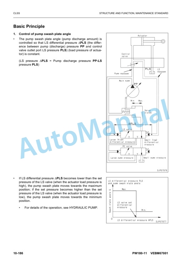
- 4.30. CLSS
- 4.31. Centre swivel joint
- 4.32. Travel PPC pedal
- 4.33. Work equipment Swing PPC valve
- 4.34. Solenoid valve block with integrated ATT EPC
- 4.35. Bucket to 2ATT
- 4.36. Boom safety valve
- 4.37. Boom floating
- 4.38. Hydraulic cylinder
- 4.39. Work equipment
- 4.40. Tool control
- 4.41. ECSS
- 4.42. Breaker return valve
- 4.43. Air conditioner
- 4.44. Electrical wiring diagram
- 4.45. Electrical system
- 4.46. Engine controller
- 4.47. Pump controller
- 4.48. Machine control system diagram
- 4.49. Machine monitor system
- 4.50. KOMTRAX system
- 4.51. KomVision system
- 4.52. KomVision controller
- 4.53. Overload warning device
- 4.54. Sensor
- 4.55. PPC levers
- 4.56. t attachment circuit hydraulic performance (main valve bypassed)
- 4.57. Travel system
- 4.58. Lubrication diagrams
- 5. STANDARD VALUE TABLE
- 5.1. Standard value table for engine related parts
- 5.2. Standard value table for chassis related parts
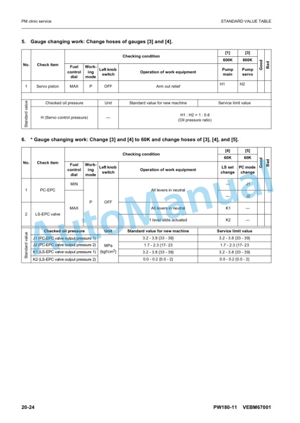
- 5.3. PM clinic service
- 6. TESTING AND ADJUSTING
- 6.1. Abbreviation list
- 6.2. Engine and cooling system
- 6.3. Handling fuel system parts
- 6.4. Releasing residual pressure from fuel system
- 6.5. Clean AdBlue/DEF tank
- 6.6. Measurement of clearance in swing circle bearing
- 6.7. Inspection and adjustment of hydraulic oil pressure in hydraulic circuit for work equipment, swing and travel
- 6.8. Inspection and adjustment of control circuit oil pressure
- 6.9. Inspection and adjustment of pump PC (valve inlet) control oil pressure
- 6.10. Inspection and adjustment of pump LS differential pressure
- 6.11. Measurement of solenoid valve output pressure
- 6.12. Adjustment of work equipment and swing PPC valve
- 6.13. Measuring and adjusting quick coupler control valve output pressure
- 6.14. Testing travel motor relief pressure
- 6.15. Testing propshaft speed
- 6.16. Testing transmission clutch control circuit
- 6.17. Inspection of locations of hydraulic drift of work equipment
- 6.18. Release of remaining pressure in hydraulic circuit
- 6.19. Measurement of oil leakage
- 6.20. Air bleeding of various parts
- 6.21. Inspection procedures for diode
- 6.22. Electrical system
- 6.23. Inspection and adjustment of ECSS (ACCU pressure)
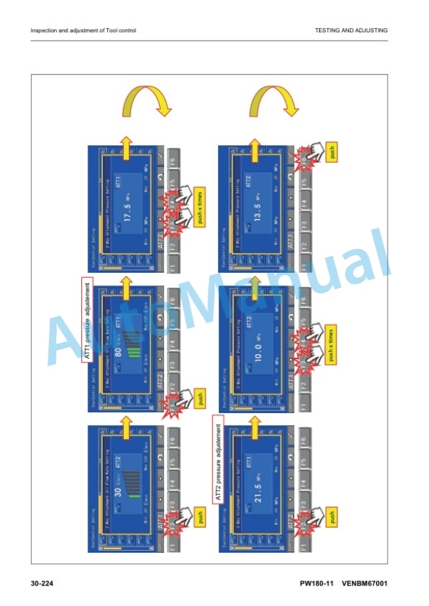
- 6.24. Inspection and adjustment of Tool control
- 6.25. Changing the lubrication interval times
- 6.26. Changing the Joystick steering control
- 6.27. Adjust rearview camera angle
- 6.28. Adjust KomVision camera angle
- 6.29. Method for adjusting KomVision camera angle
- 6.30. Adjust KomVision related items
- 7. TROUBLESHOOTING
- 7.1. Troubleshooting
- 7.2. Troubleshooting by failure code (Display of code)
- 7.3. Failure code DB30KR Joystick steering controller malfunction
- 7.4. Failure code DA22KK Pump solenoid power low error
- 7.5. Failure code DCS2KK Machine controller solenoid power voltage low error
- 7.6. Failure code DWB5KY Hot short circuit in 4th outrigger solenoid
- 8. DISASSEMBLY AND ASSEMBLY (preliminary version)
- 8.1. FRONT AXLE
- 8.2. REAR AXLE
- 8.3. TRANSMISSION
- 9. OTHER
- 9.1. Hydraulic circuit diagram
- 9.2. Elektric circuit diagram
- 9.3. Connector diagram



There are no reviews yet.