
Description
-
Model List:
- SK510-5 Skid Steer Loader
- 1. Index and foreword
- 1.1. Contents
- 1.2. Foreword and general information
- 1.2.1. Safety notice
- 1.2.2. How to read the shop manual
- 1.2.3. Explanation of terms for maintenance standard
- 1.2.4. Handling of hydraulic components
- 1.2.5. Method of disconnecting and connecting pushpull type coupler
- 1.2.6. Handling of electric equipment
- 1.2.7. How to read electric wire code
- 1.2.8. Precautions when performing work
- 1.2.9. Standard tightening torque table
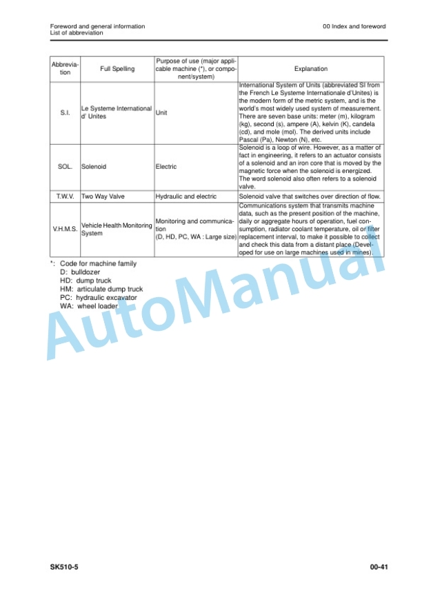
- 1.2.10. List of abbreviation
- 1.2.11. Conversion table
- 2. Specification
- 2.1. Contents
- 2.2. Specification
- 2.2.1. Standard machine overall dimensions
- 2.2.2. Machine overall dimensions with optional equipment
- 2.2.3. Specifications
- 2.2.4. Table of weight
- 2.2.5. Fuel, coolant and lubricants
- 2.3. Shop Manual
- 3. Structure, function and maintenance standard
- 3.1. Solenoid valve group ST1
- 3.2. Accumulator
- 3.3. PPC valve
- 3.3.1. Equipment control
- 4. Standard value table
- 4.1. Contents
- 4.2. Standard value table
- 4.2.1. Engine
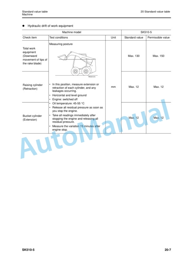
- 4.2.2. Machine
- 5. Testing and adjusting
- 5.1. Contents
- 5.2. Testing and adjusting
- 5.2.1. Special tools
- 5.2.2. Checking the engine speed
- 5.2.3. Adjustment of valve clearance
- 5.2.4. Measurement of the compression pressure
- 5.2.5. Control and adjustment of the fan belt tension
- 5.2.6. Control and adjustment of the injection timing
- 5.2.7. Checking engine oil pressure
- 5.2.8. Adjusting the stroke of the accelerator cables
- 5.2.9. Adjusting the position of the servocontrol
- 5.2.10. Testing and adjustment of gearing chain tension
- 5.2.11. Control and regulation of the pressures in the hydraulic circuits
- 5.2.12. Testing the hydraulic pump
- 5.2.13. Checking the travel deviation
- 5.2.14. Control valve
- 5.2.15. Control and regulation of the servocontrol power supply
- 5.2.16. Elimination of residual pressures pressurisation of the tank
- 5.2.17. Bleeding air from the hydraulic circuits
- 6. Disassembly and assembly
- 6.1. Contents
- 6.2. How to read the manual
- 6.3. Coating materials list
- 6.4. Removal and installation of engine hood
- 6.5. Tilting and lowering of cab
- 6.6. Removal and installation of battery
- 6.7. Removal and installation of starting motor
- 6.8. Removal and installation of alternator
- 6.9. Removal and installation of muffler
- 6.10. Removal and installation of air intake filter
- 6.11. Removal and installation of valve cover
- 6.12. Removal and installation of nozzle holder
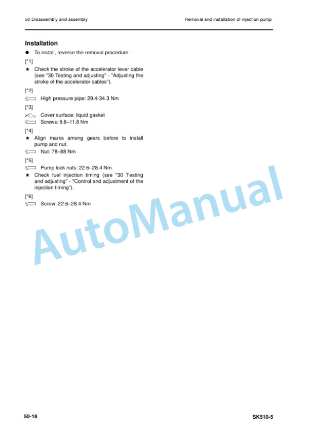
- 6.13. Removal and installation of injection pump
- 6.14. Removal and installation of cylinder head
- 6.15. Removal and installation of coolant liquid pump
- 6.16. Removal and installation of radiator group
- 6.17. Removal and installation of fuel tank
- 6.18. Removal and installation of cab
- 6.19. Removal and installation of enginepump group
- 6.20. Removal and installation of hydraulic pump assembly
- 6.21. Removal and installation of gear pump
- 6.22. Removal and installation of enginepump coupling
- 6.23. Removal and installation of control valve
- 6.24. Removal and installation of PPC valve
- 6.25. Removal and installation of hub wheel
- 6.26. Disassembly and assembly of wheel hub
- 6.27. Removal and installation of final drive
- 6.28. Removal and installation of lift cylinder
- 6.29. Removal and installation of bucket cylinder
- 6.30. Disassembly and assembly of work equipment cylinders
- 6.31. Removal and installation work equipment assembly
- 6.32. Removal and installation of equipment support frame
- 7. Diagrams and drawings
- 7.1. Contents
- 7.2. Hydraulic diagrams
- 7.2.1. Hydraulic diagram (standard)
- 7.2.2. Hydraulic diagram (road homologation)
- 7.3. Electrical circuit diagrams
- 7.3.1. Engine line p/n 37D0611310 (1/3)
- 7.3.2. Engine line p/n 37D0611310 (2/3)
- 7.3.3. Engine line p/n 37D0611310 (3/3)
- 7.3.4. Frame line p/n 37D0611330 (1/2)
- 7.3.5. Frame line p/n 37D0611330 (2/2)
- 7.3.6. Cabin line p/n 37D0611730 (1/4)
- 7.3.7. Cabin line p/n 37D0611730 (2/4)
- 7.3.8. Cabin line p/n 37D0611730 (3/4)
- 7.3.9. Cabin line p/n 37D0611730 (4/4)
- 7.3.10. Cabin line p/n 37D0611731 (1/4)
- 7.3.11. Cabin line p/n 37D0611731 (2/4)
- 7.3.12. Cabin line p/n 37D0611731 (3/4)
- 7.3.13. Cabin line p/n 37D0611731 (4/4)
- 7.3.14. Cabin line p/n 37D0611732 (1/4)
- 7.3.15. Cabin line p/n 37D0611732 (2/4)
- 7.3.16. Cabin line p/n 37D0611732 (3/4)
- 7.3.17. Cabin line p/n 37D0611732 (4/4)
- 7.3.18. Topcabin light standard p/n 37A0611471 (1/2)
- 7.3.19. Topcabin light standard p/n 37A0611471 (2/2)
- 7.3.20. Topcabin light road homologation p/n 37A0611391 / 37A0611392 (1/2)
- 7.3.21. Topcabin light road homologation p/n 37A0611391 / 37A0611392 (2/2)
- 7.3.22. Komtrax line p/n 42N0613720 (1/2)
- 7.3.23. Komtrax line p/n 42N0613720 (2/2)


There are no reviews yet.