
Description
-
Model List:
- WA600-8 Wheel Loader
- 1. Cover
- 2. Contents
- 3. Outline of separation
- 4. Dimensions of main components
- 5. Layout of work space
- 6. Assembly general schedule
- 7. Facility and jigs to be used
- 8. Oil, grease and paint
- 9. Assembly procedure
- 9.1. No. 0010 Oil, grease and coolant
- 9.2. No. 0020 Amount of oil, grease and coolant
- 9.3. No. 0030 Placing of bare machine (tireless specification)
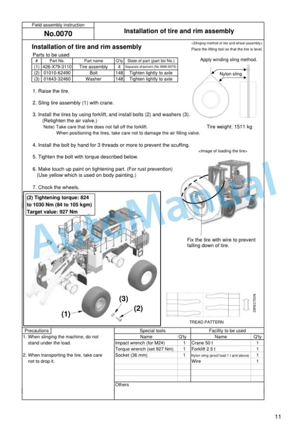
- 9.4. No. 0070 Installation of tire and rim assembly
- 9.5. No. 0080 Installation of radio antenna
- 9.6. No. 0082 Installation of KOMTRAX Plus antenna
- 9.7. No. 0084 Installation of ORBCOMM antenna
- 9.8. No. 0085 Removal of cab accessory
- 9.9. No. 0090 Installation of cab (1)
- 9.10. No. 0095 Removal of cab harness bracket
- 9.11. No. 0100 Installation of cab (2) (AJSS specification)
- 9.12. No. 0115 Installation of cab (2) (AJSS and steering wheel specification)
- 9.13. No. 0120 Installation of cab (3)
- 9.14. No. 0130 Installation of cab (4) (AJSS specification)
- 9.15. No. 0145 Installation of cab (6) (AJSS and steering wheel specification)
- 9.16. No. 0150 Installation of cab harness (1)
- 9.17. No. 0160 Installation of cab harness (2)
- 9.18. No. 0170 Installation of cab harness (3)
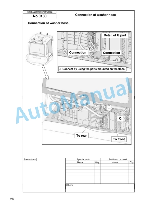
- 9.19. No. 0180 Connection of washer hose
- 9.20. No. 0190 Connection and fixing of KOMTRAX Plus harness
- 9.21. No. 0195 Installation of A/C duct
- 9.22. No. 0200 Installation of cab duct
- 9.23. No. 0210 Installation of air conditioner box piping
- 9.24. No. 0220 Installation of filter
- 9.25. No. 0230 Installation of filter box cover
- 9.26. No. 0240 Installation of duct lower cover
- 9.27. No. 0250 Installation of duct cover
- 9.28. No. 0260 Installation of utility box
- 9.29. No. 0270 Installation of cab duct cover
- 9.30. No. 0280 Installation of relay cover
- 9.31. No. 0290 Fixing of ORBCOMM cable (ORBCOMM specification)
- 9.32. No. 0300 Installation of right side rear cover
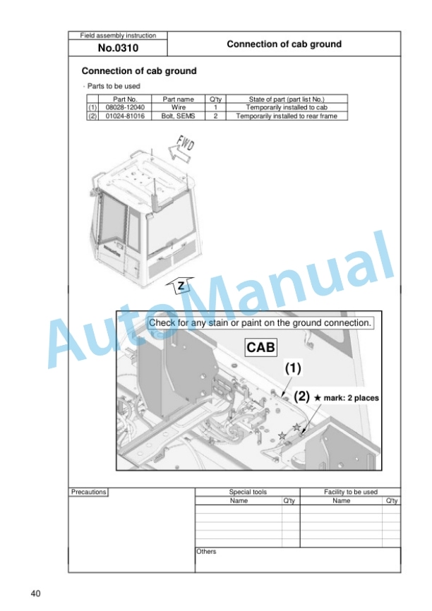
- 9.33. No. 0310 Connection of cab ground
- 9.34. No. 0400 Installation of stacked muffler
- 9.35. No. 0500 Installation of rear access ladder
- 9.36. No. 0505 Installation of right access ladder
- 9.37. No. 0510 Installation of L.H. hand rail
- 9.38. No. 0515 Installation of hand rail
- 9.39. No. 0520 Adjustment of rearview mirror
- 9.40. No. 1000 Check each part
- 9.41. No. 1010 Air bleeding of work equipment hydraulic circuit and each cylinders
- 9.42. No. 1020 Starting engine (1)
- 9.43. No. 1030 Air bleeding of brake
- 9.44. No. 1200 Installation of bucket (1)
- 9.45. No. 1210 Installation of bucket (2)
- 9.46. No. 1220 Installation of bucket (3)
- 9.47. No. 1300 Greasing (1st time)
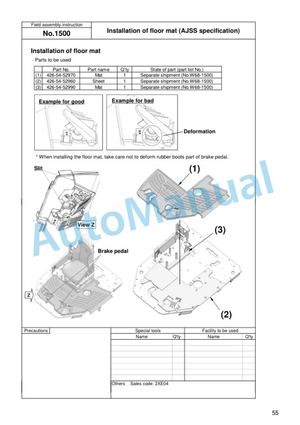
- 9.48. No. 1500 Installation of floor mat (AJSS specification)
- 9.49. No. 1600 Greasing (2nd time)
- 9.50. No. 1700 Touch up work
- 9.51. No. 9000 Default Monitor panel and switch
- 9.52. No. 9010 Default Service menu.
- 9.53. No. 9020 Default Optional device selection
- 9.54. No. 9030 Default Load meter unloaded adjustment (1)
- 9.55. No. 9040 Default Load meter unloaded adjustment (2)
- 10. Appendix Field assembly inspection report











There are no reviews yet.