

Description
-
Model List:
- WF450-3 Trash Compactor
- WF450T-3 Trash Compactor
- 1. WF4503 / WF450T3
- 2. CONTENTS
- 3. SAFETY
- 3.1. Safety notice
- 3.1.1. Preparations for work
- 3.1.2. Precautions during work
- 3.2. Foreword
- 3.3. How to read the shop manual
- 3.3.1. Volumes
- 3.3.2. Distribution and updating
- 3.3.3. Filing method
- 3.3.4. Symbols
- 3.4. Hoisting instructions
- 4. STRUCTURE AND FUNCTION
- 4.1. Power train
- 4.2. Transmission
- 4.3. Transmission solenoid valve
- 4.4. Axle
- 4.4.1. Front axle
- 4.4.2. Rear axle
- 4.5. Differential
- 4.5.1. Front differential
- 4.5.2. Rear differential
- 4.6. Final drive
- 4.7. Axle mount, center hinge pin
- 4.8. Steering piping
- 4.9. Brake piping
- 4.10. Brake
- 4.11. Parking brake
- 4.12. Hydraulic component layout
- 4.13. Work equipment lever linkage
- 4.13.1. Operation of PPC valve at neutral
- 4.13.2. Function of PPC valve
- 4.14. Cutoff valve
- 4.14.1. WF4503
- 4.14.2. Operation of cutoff valve
- 4.15. Main control valve
- 4.15.1. WF450T3
- 4.15.2. WF4503
- 4.15.3. Main relief valve
- 4.15.4. Safety valve (with suction)
- 4.15.4.1. Operation
- 4.15.5. Suction valve
- 4.15.6. Float selector valve and unload valve
- 4.15.6.1. WF4503
- 4.15.7. Operation WF450T3
- 4.15.8. Operation WF4503
- 4.16. Bucket positioner and boom kickout
- 4.16.1. WF4503
- 4.16.1.1. Operation of proximity switch
- 4.16.1.2. Operation of proximity switch
- 4.17. Air conditioner
- 4.17.1. Air conditioner piping
- 4.18. Machine monitor system
- 4.19. Main monitor
- 4.19.1. Main monitor display function
- 4.19.2. Main monitor switch function
- 4.19.3. Preheating output function
- 4.19.4. Trouble data display mode (When optional controller are installed)
- 4.20. Maintenance monitor
- 4.20.1. Maintenance monitor display function
- 4.21. Engine starting circuit
- 4.22. Engine stop circuit
- 4.23. Preheating circuit
- 4.23.1. (Automatic preheating system)
- 4.24. Electric transmission control
- 4.24.1. WF450T3
- 4.24.2. WF4503
- 4.24.3. Combination switch
- 4.25. Kickdown switch
- 4.25.1. WF4503
- 4.25.1.1. Kickdown switch
- 4.26. Kickdown electric circuit diagram
- 4.26.1. WF4503
- 4.26.1.1. Normal operation
- 4.26.1.2. Kickdown switch operated (case I)
- 4.26.1.3. Canceling actuation of kickdown switch (Case I)
- 4.26.1.4. Canceling actuation of kickdown switch (Case II)
- 4.26.1.5. Canceling actuation of kickdown switch (Case III)
- 4.27. Standard value table for engine
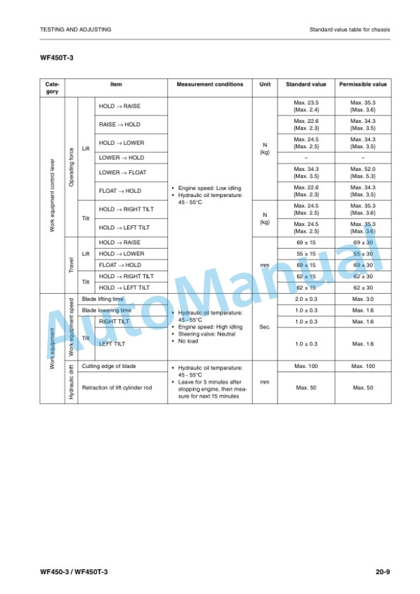
- 4.28. Standard value table for chassis
- 4.29. Standard value table for electrical parts
- 5. TESTING AND ADJUSTING
- 5.1. Tools for testing, adjusting, and troubleshooting
- 5.2. Testing steering wheel
- 5.2.1. Measuring play of steering wheel
- 5.2.2. Measuring operating force of steering wheel
- 5.2.3. Measuring operating time for steering wheel
- 5.3. Testing and adjusting steering control
- 5.4. Measuring steering oil pressure
- 5.5. Testing and adjusting accumulator charge pressure
- 5.6. Testing drop in wheel brake oil pressure
- 5.7. Measuring brake disc wear
- 5.8. Bleeding air from brake system
- 5.9. Measuring parking brake performance
- 5.10. Testing and adjusting work equipment hydraulic pressure
- 5.10.1. WF450T3
- 5.11. Measuring PPC hydraulic pressure
- 5.11.1. WF450T3
- 5.12. Measuring work equipment
- 5.12.1. WF450T3
- 5.13. Measuring hydraulic drift of work equipment
- 5.13.1. WF450T3
- 5.14. Adjusting main monitor (speedometer module)
- 6. TROUBLESHOOTING
- 6.1. Outline
- 7. TROUBLESHOOTING OF HYDRAULICAL AND MECHANICAL SYSTEM (H MODE)
- 7.1. Work Equipment WF450T3
- 7.1.1. H1 Blade does not rise
- 7.1.2. H2 Blade movement is slow or blade lacks lifting power
- 7.1.3. H3 When blade is raised, it moves slowly at a certain height
- 7.1.4. H4 Blade cannot be pushed with lift cylinder (blade floats)
- 7.1.5. H5 Excessive hydraulic drift of blade
- 7.1.6. H6 Blade and straight frame shake during operation
- 7.1.7. H7 Blade drops momentarily when control lever is operated from HOLD to RAISE
- 7.1.8. H8 Blade does not tilt
- 7.1.9. H9 Blade movement is slow or tilt lacks power
- 7.1.10. H10 Blade movement becomes slow during tilt operation
- 7.1.11. H11 Blade cannot be pushed with tilt cylinder
- 7.1.12. H12 Excessive hydraulic drift of blade
- 7.1.13. H13 Blade shakes during loading operation (main control valve at HOLD)
- 7.1.14. H14 Blade tilts momentarily to left when control lever is operated from HOLD to RIGHT TILT
- 7.1.15. H15 Blade control lever is heavy or does not move smoothly
- 7.2. Steering system
- 7.2.1. H16 Steering does not turn
- 7.2.2. H17 Steering wheel is heavy
- 7.2.3. H18 Steering wheel wobbles or there is excessive shock
- 7.2.4. H19 Machine steers to one side when traveling
- 7.2.5. H20 Turning radius to left and right is different
- 8. DISASSEMBLY AND ASSEMBLY
- 8.1. Special tool list
- 8.2. Removal and installation of rear axle assembly
- 8.3. Removal and installation of hydraulic pump, PPC pump assembly
- 8.3.1. WF4503
- 8.3.2. WF450T3
- 8.4. Disassembly and assembly of hydraulic cylinder assembly
- 8.4.1. WF4503
- 8.4.2. WF450T3
- 8.5. Main control valve assembly
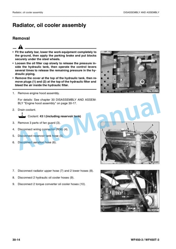
- 8.6. Radiator, oil cooler assembly
- 8.6.1. Removal
- 8.6.2. Installation
- 8.7. Engine hood assembly
- 8.7.1. Removal
- 8.7.2. Installation
- 8.8. Lift cylinder assembly
- 8.8.1. Removal
- 8.8.2. Installation
- 8.9. Tilt cylinder assembly
- 8.9.1. Removal
- 8.9.2. Installation
- 8.10. Work equipment assembly
- 8.10.1. Removal
- 8.10.2. Installation
- 8.10.3. Assembly
- 8.11. Front axle assembly
- 8.11.1. Removal (WF4503)
- 8.11.2. Installation (WF4503)
- 8.11.3. Removal (WF450T3)
- 8.11.4. Installation (WF450T3)
- 8.12. Removal and installation of rear axle assembly
- 8.13. Front differential assembly
- 8.13.1. Removal
- 8.13.2. Installation
- 8.14. Differential Assembly
- 8.14.1. Disassembly
- 8.14.2. Assembly
- 9. MAINTENANCE STANDARD
- 9.1. Engine mount, transmission mount
- 9.2. Torque converter
- 9.3. Transmission
- 9.3.1. (1/2)
- 9.3.2. (2/2)
- 9.3.3. Forward, 1st clutch
- 9.3.4. d, reverse clutch
- 9.3.5. d, 4th clutch
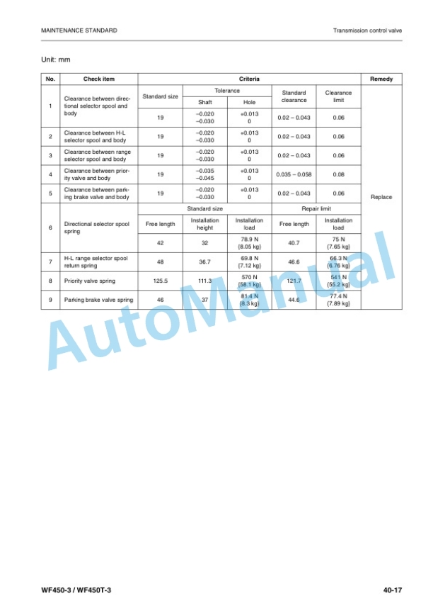
- 9.4. Transmission control valve
- 9.4.1. Modulation valve assembly
- 9.4.2. Upper valve assembly
- 9.4.3. Lower valve assembly
- 9.4.4. Flow valve
- 9.4.5. Accumulator valve
- 9.5. Drive shaft
- 9.6. Differential
- 9.7. Limited slip differential
- 9.8. Final drive
- 9.9. Axle mount
- 9.10. Center hinge pin
- 9.11. Steering column
- 9.12. Steering valve
- 9.13. Steering cylinder mount
- 9.14. Torque converter, transmission pump
- 9.14.1. SAR(3) 100
- 9.15. Steering, switch pump
- 9.15.1. SAR(3)71 50
- 9.16. Hydraulic, PPC pump
- 9.16.1. WF450T3 SAR(3)80 (1) 28
- 9.16.2. WF4503 SAR(4)140 (1) 28
- 9.17. Main control valve
- 9.18. Bucket cylinder
- 9.18.1. WF4503
- 9.19. Work equipment linkage
- 9.19.1. WF450T3
- 9.19.2. WF4503
- 9.20. Bucket positioner and boom kickout
- 9.20.1. WF4503
- 10. OTHERS
- 10.1. Transmission hydraulic circuit diagram
- 10.2. Brake hydraulic circuit diagram
- 10.3. Work equipment hydraulic circuit diagram (WF450T3)
- 10.4. Work equipment hydraulic circuit diagram (WF4503)
- 10.5. Electric circuit diagram 1/4) (WF450T3)
- 10.6. Electric circuit diagram 2/4) (WF450T3)
- 10.7. Electric circuit diagram 3/4) (WF450T3)
- 10.8. Electric circuit diagram 4/4) (WF450T3)
- 10.9. Electric circuit diagram 1/4) (WF4503)
- 10.10. Electric circuit diagram 2/4) (WF4503)
- 10.11. Electric circuit diagram 3/4) (WF4503)
- 10.12. Electric circuit diagram 4/4) (WF4503)




There are no reviews yet.