
Description
-
Model List:
- V12-04
- V12AC
- V12N
- 1. Regular testing
- 1.1. Table of content
- 1.2. Regular testing
- 1.2.1. Basic principles
- 1.3. Electric motor
- 1.3.1. Test steps for the electric traction motor
- 1.4. Chassis drivers compartment
- 1.4.1. Test steps for the chassis
- 1.4.2. Test steps for the raisable drivers compartment
- 1.4.3. Test steps for the nonraisable drivers compartment
- 1.5. Steering system
- 1.5.1. Test steps for the steering
- 1.5.2. Test steps for the steering motor
- 1.6. Guidance
- 1.6.1. Test steps for guidance
- 1.7. Wheels and tyres
- 1.7.1. Test steps for Vulkollan tyres
- 1.8. Brake system
- 1.8.1. Test steps for the brake system
- 1.8.2. Checking the braking power of the service brake
- 1.8.3. Required braking capabilities for group C industrial trucks
- 1.9. Operating devices
- 1.9.1. Test steps for operating devices
- 1.10. Electrical enclosure
- 1.10.1. Test steps for electrical equipment
- 1.10.2. Test steps for the battery and battery connection assemblies
- 1.11. Hydraulics
- 1.11.1. Test steps for the hydraulic system
- 1.11.2. Test steps for the pump motor
- 1.12. Lift mast
- 1.12.1. Test steps for the lift mast
- 1.13. Load support
- 1.13.1. Test steps for load chains
- 1.13.2. Test steps for the fork arms
- 1.14. Attachment
- 1.14.1. Test steps for the standard attachment
- 1.14.2. Test steps for retrofitted attachments and other lifting accessories
- 1.15. Special equipment.accessories
- 1.15.1. Test steps for other accessories
- 1.15.2. Test steps for the onboard charging system
- 1.15.3. Test steps for the cold store cabWind deflector cab
- 1.15.4. Test steps for the abseil system
- 1.15.5. Test steps for the fall protection system
- 1.15.6. Test steps for assistance systems
- 2. Service case Release tools for contacts
- 2.1. Table of content
- 2.2. Safety information
- 2.2.1. Safety information for repair and maintenance work
- 2.3. Information
- 2.3.1. Information
- 2.4. Overview
- 2.4.1. Overview of service cases
- 2.5. Plug systems
- 2.5.1. ATS 2.8 plug connector
- 2.5.2. CMC plug connector
- 2.5.3. DCS 9.5 plug connector
- 2.5.4. DIN 1.5mm circular connector
- 2.5.5. DIN 2.5mm circular connector
- 2.5.6. Deutsch DTM plug connector
- 2.5.7. ECU appliance plug
- 2.5.8. MCON appliance plug
- 2.5.9. Appliance plug with JPT and MQS contacts
- 2.5.10. Appliance plug with MT2 and JPT contacts
- 2.5.11. SICMA appliance plug
- 2.5.12. Econoseal JMark 2 plug connector
- 2.5.13. Elobau 11pin receptacle housing
- 2.5.14. E5931 plug connector
- 2.5.15. FASTINFASTON 6.3mm plug connector
- 2.5.16. GT150 plug connector
- 2.5.17. HDSCS plug connector
- 2.5.18. JPT plug connector
- 2.5.19. JPT SLD plug connector
- 2.5.20. JPT plug connector Saab
- 2.5.21. JPT plug connector VW
- 2.5.22. Kompakt 1.1 plug connector
- 2.5.23. Bosch Kompakt 4 plug connector
- 2.5.24. Leavyseal plug connector
- 2.5.25. MCON 1.2mm LL plug connector
- 2.5.26. MCON 1.2mm CB plug connector
- 2.5.27. MCP plug connector
- 2.5.28. MetriPack 150 plug connector
- 2.5.29. MiniFit plug connector
- 2.5.30. Mini Universal MATENLOK plug connector
- 2.5.31. Mini relay socket for DFK 1.3 and MDK 1.3
- 2.5.32. MKR Plus plug connector
- 2.5.33. MQS plug connector
- 2.5.34. MR plug connector
- 2.5.35. MTA plug housing and fuse housing
- 2.5.36. MT2 plug connector
- 2.5.37. MT2 1.5mm plug connector VW
- 2.5.38. Multilock plug connector
- 2.5.39. MX150 plug connector
- 2.5.40. NG1 plug connector
- 2.5.41. Phönix Contact HC plug connector
- 2.5.42. PT 3F plug connector
- 2.5.43. Relay socket with SPT contacts for DFK 1.3.4 and MDK 1.3.4
- 2.5.44. Relay socket with SPT and MPT contacts
- 2.5.45. Fuse holder with SPT contacts
- 2.5.46. Sicma plug connector
- 2.5.47. SLK 2.8 plug connector
- 2.5.48. Souriau UTL7 plug connector
- 2.5.49. Superseal 1.5mm plug connector
- 2.5.50. Trident Neptune plug connector
- 2.5.51. Universal MATENLOK plug connector
- 2.5.52. VW 9.5mm plug connector
- 3. High level order pickerV11ac, V12ac
- 3.1. Table of content
- 3.2. Product information
- 3.2.1. General product information
- 3.3. Diagnostics
- 3.3.1. Diagnostics
- 3.3.2. Software
- 3.3.3. Error lists
- 3.3.4. Teachin
- 3.4. Electric motor
- 3.4.1. Traction motor
- 3.4.2. Rev sensor
- 3.4.3. Temperature sensor
- 3.5. Mechanical drive axle
- 3.5.1. Front bevel gears
- 3.6. Steering
- 3.6.1. Electric steering
- 3.7. Mechanical guidance
- 3.7.1. Guide elements
- 3.7.2. Aisle detection
- 3.8. Inductive guidance
- 3.8.1. Inductive guidance
- 3.8.2. Central unit
- 3.8.3. Peripherals
- 3.8.4. Aisle detection
- 3.8.5. Steering angle limiter (LWB)
- 3.9. Wheels and tyres
- 3.9.1. Wheels
- 3.10. Brake system
- 3.10.1. Brake system
- 3.10.2. Electric service brake
- 3.10.3. Parking brake
- 3.11. Controls
- 3.11.1. Operating panel
- 3.12. Electrics . Electronics
- 3.12.1. Wiring
- 3.12.2. Electrical system
- 3.12.3. Sensor system
- 3.12.4. Other components
- 3.13. Electronic controllers
- 3.13.1. Drive.pump controller (FPS) A10
- 3.13.2. Other electronic controllers
- 3.14. Hydraulics, general
- 3.14.1. Basic hydraulics
- 3.15. Valves
- 3.15.1. Pressure relief valve
- 3.15.2. Directional control valve
- 3.15.3. Proportional valve
- 3.15.4. Valve elements
- 3.15.5. Valve block
- 3.16. Load lift system
- 3.16.1. Lift mast bracing
- 3.16.2. Lift mast bearing
- 3.17. Lift mast
- 3.17.1. Lift cylinder
- 3.18. Special equipment, very narrow aisle trucks
- 3.18.1. End of aisle slow down and stop (ZAG)
- 3.19. Other accessories
- 3.19.1. Devices
- 4. Manual for qualified personsV10, V11, V12, K
- 4.1. Table of content
- 4.2. Description
- 4.2.1. Skylotec abseil system
- 4.3. Application
- 4.3.1. Preparation
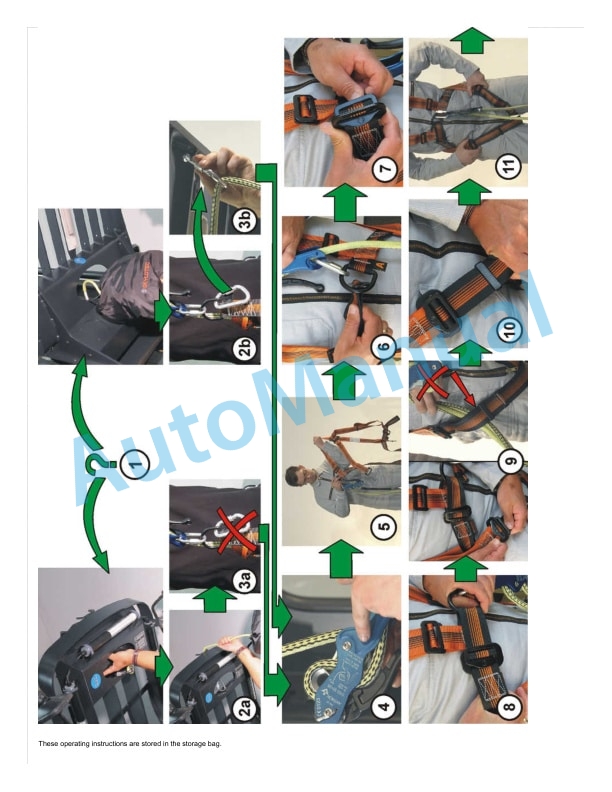
- 4.3.2. Fastening the harness
- 4.3.3. Exiting the drivers cab
- 4.3.4. Operation
- 4.3.5. Followup work
- 4.4. Maintenance and testing
- 4.4.1. Maintenance
- 4.4.2. Regular testing
- 5. Mobile personal protection system
- 5.1. Table of content
- 5.2. Mobile personal protection system
- 5.2.1. Functionality of an MPSE
- 5.2.2. MPSE operating status
- 5.2.3. Interface for the truck control unit
- 5.3. System description
- 5.3.1. Functions
- 5.3.2. Warehouse configuration
- 5.3.3. Block diagram
- 5.4. Commissioning
- 5.4.1. Daily commissioning
- 5.4.2. Initial commissioning
- 5.5. Component descriptions
- 5.5.1. MGAL controller
- 5.5.2. Distance measuring instrument
- 5.5.3. Reflective light switch
- 5.5.4. Magnetoperated switches
- 5.6. Detectors
- 5.6.1. Laser scanner
- 5.7. Maintenance
- 5.7.1. Maintenance and testing
- 5.8. Diagnostics system
- 5.8.1. Diagnostic software
- 5.8.2. Diagnostics
- 5.8.3. Error list
- 6. Mobile personal protection system
- 6.1. Table of content
- 6.2. Mobile personal protection system
- 6.2.1. General
- 6.2.2. Functionality of the personal protection system
- 6.3. Commissioning
- 6.3.1. Daily commissioning tasks
- 6.3.2. Initial commissioning tasks
- 6.4. Component descriptions
- 6.4.1. Block diagram
- 6.4.2. PSA controller
- 6.4.3. Interface to the industrial truck
- 6.4.4. Displacement transducer
- 6.4.5. Reflective light barriers
- 6.4.6. Reflectors
- 6.4.7. Magnetoperated switch
- 6.4.8. Laser scanner
- 6.5. Maintenance
- 6.5.1. Maintenance and testing
- 6.6. Diagnostics
- 6.6.1. Diagnostics


There are no reviews yet.