

Description
-
Model List:
- T20AP Ex3G
- T25 Ex3G
- T25AP Ex3G
- T30 Ex3G
- 1. Service case Release tools for contacts
- 1.1. Table of content
- 1.2. Safety information
- 1.2.1. Safety information for repair and maintenance work
- 1.3. Information
- 1.3.1. Information
- 1.4. Overview
- 1.4.1. Overview of service cases
- 1.5. Plug systems
- 1.5.1. ATS 2.8 plug connector
- 1.5.2. CMC plug connector
- 1.5.3. DCS 9.5 plug connector
- 1.5.4. DIN 1.5mm circular connector
- 1.5.5. DIN 2.5mm circular connector
- 1.5.6. Deutsch DTM plug connector
- 1.5.7. ECU appliance plug
- 1.5.8. MCON appliance plug
- 1.5.9. Appliance plug with JPT and MQS contacts
- 1.5.10. Appliance plug with MT2 and JPT contacts
- 1.5.11. SICMA appliance plug
- 1.5.12. Econoseal JMark 2 plug connector
- 1.5.13. Elobau 11pin receptacle housing
- 1.5.14. E5931 plug connector
- 1.5.15. FASTINFASTON 6.3mm plug connector
- 1.5.16. GT150 plug connector
- 1.5.17. HDSCS plug connector
- 1.5.18. JPT plug connector
- 1.5.19. JPT SLD plug connector
- 1.5.20. JPT plug connector Saab
- 1.5.21. JPT plug connector VW
- 1.5.22. Kompakt 1.1 plug connector
- 1.5.23. Bosch Kompakt 4 plug connector
- 1.5.24. Leavyseal plug connector
- 1.5.25. MCON 1.2mm LL plug connector
- 1.5.26. MCON 1.2mm CB plug connector
- 1.5.27. MCP plug connector
- 1.5.28. MetriPack 150 plug connector
- 1.5.29. MiniFit plug connector
- 1.5.30. Mini Universal MATENLOK plug connector
- 1.5.31. Mini relay socket for DFK 1.3 and MDK 1.3
- 1.5.32. MKR Plus plug connector
- 1.5.33. MQS plug connector
- 1.5.34. MR plug connector
- 1.5.35. MTA plug housing and fuse housing
- 1.5.36. MT2 plug connector
- 1.5.37. MT2 1.5mm plug connector VW
- 1.5.38. Multilock plug connector
- 1.5.39. MX150 plug connector
- 1.5.40. NG1 plug connector
- 1.5.41. Phönix Contact HC plug connector
- 1.5.42. PT 3F plug connector
- 1.5.43. Relay socket with SPT contacts for DFK 1.3.4 and MDK 1.3.4
- 1.5.44. Relay socket with SPT and MPT contacts
- 1.5.45. Fuse holder with SPT contacts
- 1.5.46. Sicma plug connector
- 1.5.47. SLK 2.8 plug connector
- 1.5.48. Souriau UTL7 plug connector
- 1.5.49. Superseal 1.5mm plug connector
- 1.5.50. Trident Neptune plug connector
- 1.5.51. Universal MATENLOK plug connector
- 1.5.52. VW 9.5mm plug connector
- 2. Extest recording for ignition protection types
- 3. Explosion protection
- 3.1. Table of content
- 3.2. Basic principles
- 3.2.1. ATEX
- 3.2.2. Implementing the directives into national law
- 3.2.3. Conformity assessment procedures
- 3.2.4. EU type approval
- 3.2.5. Notified bodies
- 3.2.6. Explosion protection measures
- 3.2.7. Fires and explosion conditions
- 3.2.8. Potential sources of ignition
- 3.2.9. Potentially explosive area
- 3.2.10. Hazardous quantities
- 3.2.11. Explosion limits
- 3.2.12. Zones for potentially explosive areas
- 3.2.13. Classification as equipment for potentially explosive atmospheres
- 3.2.14. Classification as electrical equipment for potentially explosive atmospheres
- 3.2.15. Equipment categories
- 3.2.16. Equipment Protection Level (EPL)
- 3.2.17. Identification
- 3.2.18. Assignment of zones, equipment category and protection level
- 3.2.19. Protection types provided by housings with an IP code
- 3.2.20. Significant temperatures
- 3.3. Spark protection
- 3.3.1. Overview
- 3.3.2. Flameproof enclosure Ex d
- 3.3.3. Increased safety Ex e
- 3.3.4. Intrinsic safety Ex i
- 3.3.5. Type of spark protection Ex n
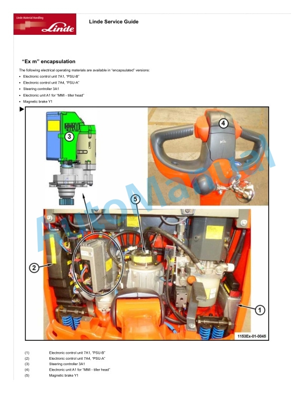
- 3.3.6. Encapsulation Ex m
- 3.3.7. Equipment dust explosion protection by enclosures Ex t
- 3.3.8. Constructional safety Ex c
- 3.3.9. Protection against static electricity
- 3.4. Safety electronics
- 3.4.1. Receiver
- 3.4.2. Horn control
- 3.4.3. Interface
- 3.4.4. Insulation monitoring
- 3.4.5. Fan thermostat
- 3.4.6. Proplan safety unit
- 3.4.7. REG 16 temperature control
- 3.4.8. Relay box
- 3.4.9. Transmitter
- 3.4.10. PWM monitoring system electronic control unit
- 3.4.11. THERMO 16 electronic control unit
- 3.4.12. Converter
- 3.5. Gas safety systems
- 3.5.1. Gas explosion conditions
- 3.5.2. Explosion limits
- 3.5.3. Preventing a gas explosion
- 3.5.4. Using gas safety systems
- 3.5.5. Gas safety systems on industrial trucks
- 3.5.6. Gas measurement
- 3.5.7. Gas safety systems in use
- 4. Lithiumion 24V warehouse batteries
- 4.1. Table of content
- 4.2. Product information
- 4.2.1. Foreword
- 4.2.2. Safety information
- 4.3. Service
- 4.3.1. Operating materials
- 4.4. Diagnostics
- 4.4.1. Diagnostics
- 4.5. Battery status
- 4.5.1. Status of the battery
- 4.5.2. Transport function
- 4.5.3. Under voltage protection
- 4.5.4. Waking up the battery
- 4.5.5. Heating functions
- 4.6. Deenergised system
- 4.6.1. BG 20
- 4.6.2. BG 21, BG 22
- 4.7. Design and function
- 4.7.1. Structural principle of the battery
- 4.7.2. Structural principle of the battery module
- 4.7.3. Structural principle of the technology compartment
- 4.7.4. CAN bus connections
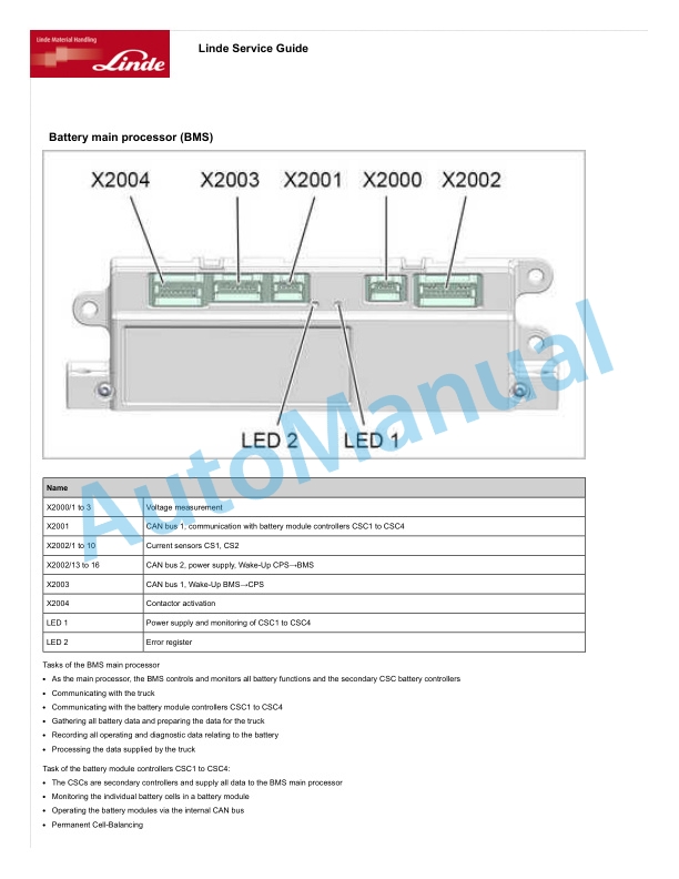
- 4.7.5. Battery main processor (BMS)
- 4.7.6. Constant power supply (CPS)
- 4.7.7. Current.voltage sensors (CVS)
- 4.7.8. Battery isolating contactor (BSD)
- 4.7.9. Electrical fuses
- 4.7.10. Pressure compensation element
- 4.8. Battery tray
- 4.8.1. Warehouse technology 1
- 4.9. Wiring
- 4.9.1. Warehouse technology
- 4.10. Technology compartment
- 4.10.1. BG 20
- 4.10.2. BG 21, BG 22
- 4.11. Battery
- 4.11.1. BG 20
- 4.11.2. BG 21, BG 22
- 5. Lithiumion 24 V warehouse batteries
- 5.1. Table of content
- 5.2. Product information
- 5.2.1. Description of lithiumion battery
- 5.2.2. Emergency procedures
- 5.2.3. Functional description
- 5.3. Service
- 5.3.1. Maintenance and repair
- 5.4. Diagnostics
- 5.4.1. Diagnostics
- 5.5. Wiring
- 5.5.1. Power cables and communication cables
- 5.5.2. Removing.installing the power cable
- 5.6. Battery access
- 5.6.1. Battery trays, warehouse technology
- 5.6.2. Removing.installing the battery
- 5.7. Compact D1.D3
- 5.7.1. Deenergised system
- 5.7.2. Structure Components
- 5.7.3. Technology compartment Components
- 5.8. NextGen F6
- 5.8.1. Deenergised system
- 5.8.2. Structure Components
- 5.8.3. Technology compartment Components
- 5.9. NextGen H9.H12
- 5.9.1. Deenergised system
- 5.9.2. Structure Components
- 5.9.3. Technology compartment Components
- 6. Pallet truckT20AP, T20APB, T25, T25AP, T30 Ex3G
- 6.1. Table of content
- 6.2. Product information
- 6.2.1. Truck information
- 6.2.2. Service
- 6.3. Running gear and drive train
- 6.3.1. Drive components
- 6.3.2. Steering system
- 6.3.3. Brake system
- 6.4. Drivers compartment
- 6.4.1. Overview of operating units and display elements
- 6.4.2. Operating units
- 6.4.3. Display elements
- 6.5. Electrics.electronics
- 6.5.1. Wiring
- 6.5.2. Electrics.electronics components
- 6.5.3. Control units
- 6.6. Hydraulics
- 6.6.1. Basic and working hydraulics
- 7. Pallet truckT20AP, T20APB, T25, T25AP, T30 Ex3G
- 7.1. Table of content
- 7.2. Product information
- 7.2.1. Truck information
- 7.2.2. Service
- 7.3. Running gear and drive train
- 7.3.1. Drive components
- 7.3.2. Steering system
- 7.4. Drivers compartment
- 7.4.1. Overview of operating units and display elements
- 7.4.2. Operating units
- 7.4.3. Display elements
- 7.5. Electrics.electronics
- 7.5.1. Wiring
- 7.5.2. Control units
- 7.6. hydraulics
- 7.6.1. Basic and working hydraulics












There are no reviews yet.