

Description
-
Model List:
- LB446HB, LB446H Light Boy
- 1. Floodlight Projector
- 1.1. FOREWORD
- 1.2. CONTENTS
- 1.3. Safety
- 1.3.1. Warning Symbols
- 1.3.2. Loading generator
- 1.3.2.1. Service Shop (Location)
- 1.3.2.2. Working Wear
- 1.3.2.3. Tools to Be Used
- 1.3.2.4. Parts
- 1.3.2.5. Bolt Tightening Torque
- 1.3.2.6. Product Handling
- 1.3.2.7. Installation
- 1.3.2.8. Transport
- 1.3.2.9. Warning Labels
- 1.4. Outline of Floodlight Projector
- 1.5. Outline of Floodlight Projector
- 1.5.1. Specifications
- 1.5.2. External View and Components of Floodlight Projector
- 1.6. Structure of Floodlight Projector
- 1.7. Structure of Floodlight Projector
- 1.7.1. Outline of Structure
- 1.7.2. Electrical Group
- 1.7.2.1. Balloon Unit
- 1.7.2.2. Lamp Stand Unit
- 1.7.2.3. Power Cable Unit
- 1.7.3. Mast Group
- 1.7.4. Outrigger group
- 1.7.5. Base Plate Group
- 1.7.5.1. Base Plate Unit
- 1.7.5.2. Steering Unit
- 1.7.5.3. Brake Unit
- 1.8. Disassembly and Assembly
- 1.9. Disassembly and Assembly
- 1.9.1. Before Starting Operation
- 1.9.1.1. Grasp of Service History
- 1.9.1.2. Preparing the Necessary Tools, Parts and Materials
- 1.9.2. Disassembly and Assembly Procedures
- 1.9.2.1. General Instructions
- 1.9.2.2. Disassembly Procedure of Each Assembly /Unit /Group
- 1.9.2.3. Disconnection of Couplers
- 1.9.2.4. Removal of Balloon Assembly
- 1.9.2.5. Removal of Lighting Unit Assembly
- 1.9.2.6. Removal of Pin (Socket) Contact
- 1.9.2.7. Removal of Stand Assembly
- 1.9.2.8. Removal of Lamp Stand Assembly
- 1.9.2.9. Unloading of Generator
- 1.9.2.10. Removal of Mast Group
- 1.9.2.11. Removal of Outrigger Group
- 1.9.2.12. Disassembly of Balloon Assembly
- 1.9.2.13. Disassembly of Stand Assembly
- 1.9.2.14. Disassembly of Lighting Unit Assembly
- 1.9.2.15. Disassembly of Lamp Stand Assembly
- 1.9.2.16. Disassembly of Power Cable Unit
- 1.9.2.17. Disassembly of Mast Group
- 1.9.2.18. Disassembly of Outrigger Group
- 1.9.2.19. Disassembly of Base Plate Unit
- 1.9.2.20. Disassembly of Steering Unit
- 1.9.2.21. Disassembly of Brake Unit
- 1.10. Inspection and Maintenance
- 1.11. Inspection and Maintenance
- 1.11.1. Electrical Group
- 1.11.1.1. Balloon Unit
- 1.11.1.2. Lamp Stand Unit
- 1.11.1.3. Replacement of Balloon Unit and Lamp Stand Unit
- 1.11.1.4. Power Cable Unit
- 1.11.2. Mast Group
- 1.11.2.1. Mast Group
- 1.11.3. Outrigger Group
- 1.11.4. Base Plate Group
- 1.11.4.1. Base Plate Unit
- 1.11.4.2. Steering Unit
- 1.11.4.3. Brake Unit
- 1.11.5. Grounding
- 1.12. Periodic Inspection Items
- 1.13. Periodic Inspection Items
- 1.13.1. Inspection Items and Intervals
- 1.14. Circuit
- 1.15. Circuit
- 1.15.1. Electrical Circuit
- 1.15.1.1. How to Read Electrical Circuit Diagram
- 1.15.1.2. Electrical Circuit Diagram
- 1.16. Tools, Instruments and Other Materials for Inspection and Maintenance
- 1.17. Tools, Instruments and Other Materials for Inspection and Maintenance
- 1.17.1. Machines, Tools and Instruments
- 1.17.1.1. General Tools
- 1.17.1.2. Special Tool
- 1.17.1.3. Measuring Instrument
- 1.17.1.4. Materials Required
- 1.18. Bolts and Nuts Tightening Torques
- 1.19. Bolts and Nuts Tightening Torques
- 1.19.1. General Instructions
- 1.19.2. Major Bolts and Nuts
- 1.20. Troubleshooting
- 1.21. Troubleshooting
- 1.21.1. Troubleshooting Procedures
- 1.22. BACKCOVER
- 2. Generator
- 2.1. Introduction
- 2.2. Contents
- 2.3. FOR SAFE OPERATION
- 2.3.1. Warning Symbols
- 2.3.2. Safety Precautions
- 2.3.2.1. General Precautions for Operation and Maintenance
- 2.3.2.2. Preventing Fires
- 2.3.2.3. Preventing Exhaust Gas Inhalation
- 2.3.2.4. Preventing Burns
- 2.3.2.5. Electric Shock, Short Circuits and Batteries
- 2.3.2.6. Processing Wastes
- 2.3.2.7. Modification not authorized
- 2.3.2.8. Installation
- 2.3.2.9. Do not use the floodlight projector on a slope.
- 2.3.2.10. Use an outrigger to prevent the floodlight projector from ov
- 2.3.2.11. Confirm the ground cable connection.
- 2.3.2.12. Transport
- 2.3.2.13. Lamp
- 2.3.2.14. Generator
- 2.3.2.15. When Lamps are On
- 2.3.2.16. Adjusting Height of Mast
- 2.3.2.17. Others
- 2.3.3. Location of Warning Labels
- 2.4. PRODUCT OVERVIEW
- 2.4.1. Intended Uses and Conditions
- 2.4.1.1. Features of Generator
- 2.4.1.2. Running Conditions
- 2.4.1.3. Mounting of Generator
- 2.4.1.4. Description of Model Name.
- 2.4.2. Specifications
- 2.4.3. Performance
- 2.4.4. Applicable fuel and Lube Oil
- 2.4.4.1. Fuel
- 2.4.4.2. Lube oil
- 2.4.5. Out view and Part names
- 2.4.6. Control Panel
- 2.4.6.1. Control Apparatus
- 2.4.6.2. Protective Device
- 2.4.7. Compornent of Generator
- 2.4.8. Electric Wiring Diagram
- 2.4.9. Precaution for Installation
- 2.4.10. How to Operate Generator
- 2.4.10.1. Checking Before Start-up
- 2.4.10.2. How to Start Generator
- 2.4.10.3. During Operation
- 2.4.10.4. How to Stop Generator
- 2.4.11. How to replace light bulb
- 2.4.11.1. Installation of lamp
- 2.5. TROUBLESHOOTING
- 2.6. List of Periodic Inspections
- 2.6.1. Diesel Generator
- 2.6.2. Floodlight Projector
- 2.7. Inspection and Adjustment of Engine
- 2.7.1. Refueling
- 2.7.2. Cleaning fuel filter
- 2.7.3. Bleeding air from fuel system
- 2.7.4. Checking and Replenishing Lube Oil
- 2.7.5. Replacing lube oil and cleaning lube oil filter. (1st time)
- 2.7.6. Replacing air cleaner element
- 2.7.7. Handling of Battery
- 2.7.8. Adjustment of Valve clearance
- 2.7.9. Inspection of Fuel injection Valve injection pressure and sp
- 2.7.10. Adjustment of fuel injection timing
- 2.7.11. Adjustments of no-load max. revolution and stopping device
- 2.8. Inspection of generator
- 2.8.1. Measurement of floodlight output terminal voltage (when the
- 2.8.2. Measurement of no-load voltage
- 2.8.3. Measurement of generator voltage (at no-load operation)
- 2.8.4. Measurement of insulation resistance
- 2.9. Trial running
- 2.10. Long -term storage
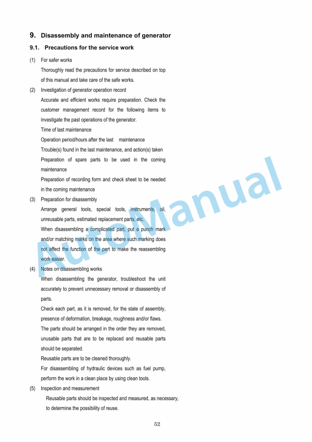
- 2.11. Disassembly and maintenance of generator
- 2.11.1. Precautions for the service work
- 2.11.2. Disassembling procedure
- 2.11.3. Reassembly procedure
- 2.12. Rotor extraction tool
- 2.13. Engine Service Standard
- 2.14. Tightening Torque
- 2.14.1. Major Bolts and Nuts
- 2.14.2. Standard Bolts and Nuts
- 2.15. INTRODUCTION
- 2.16. Service Information
- 2.17. CONTENTS
- 2.18. Specifications
- 2.18.1. Specifications
- 2.18.2. Cross Sectional Views
- 2.19. Service standard
- 2.20. Disassembly and Reassembly
- 2.20.1. Tools, Meters and Instruments
- 2.20.1.1. Tools
- 2.20.1.2. Meters, Instruments and Service Accessories
- 2.20.1.3. Instruments
- 2.20.2. Tightening Torque
- 2.20.3. Maintenace Schedule
- 2.20.4. Disassembly Procedures
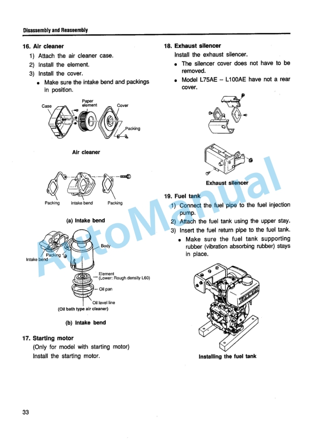
- 2.20.5. Reasembly Procedures
- 2.20.6. Recoil Starter
- 2.21. Checking and Servicing
- 2.21.1. Cylinder Head
- 2.21.2. Piston and Piston Pin
- 2.21.3. Connecting Rod
- 2.21.4. Crankshaft, Flywheel and Main Bearing
- 2.21.5. Camshaft and Tappet
- 2.21.6. Timing Gear
- 2.21.7. Crankcase Cover
- 2.21.8. Cylinder Sleeve and Cylinder Block
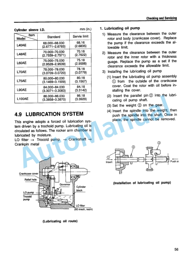
- 2.21.9. Lubrication System
- 2.21.10. Fuel System
- 2.21.11. Speed Control Device
- 2.21.12. Electrical System
- 2.21.12.1. Wiring Diagram
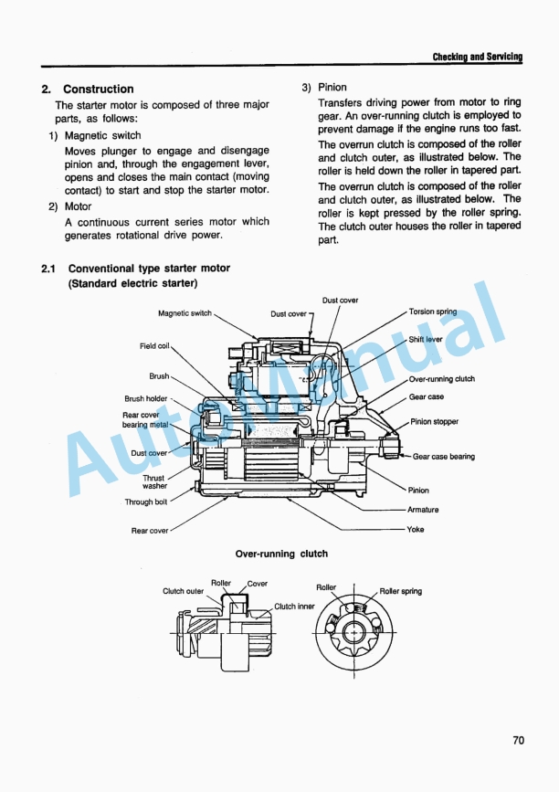
- 2.21.12.2. Starter Motor
- 2.21.12.3. Generator (Dynamo), Regulator and Rectifier
- 2.21.12.4. Air Heater
- 2.21.12.5. Battery
- 2.21.13. Adjustment
- 2.22. Toroubleshooting
- 2.23. Test Run
- 2.24. Helical Inserting Part for Repair
- 2.25. Appendix 1 Difference Between Parts under Spec. S and D
- 2.26. Appendix 2 Detail of Special Tools
- 3. Colophon
- 4. Spine Title


,%202GM(F)(L),%203GM(D)(F)(L),%203HM(F)(L)%20Marine%20Diesel%20Engine%20Service%20Manual&url=https://pdfrepairmanual.com/docs/yanmar-1gm10l-2gmfl-3gmdfl-3hmfl-marine-diesel-engine-service-manual/&media=https://pdfrepairmanual.com/wp-content/uploads/2026/01/yanmar-1gm10l-2gmfl-3gmdfl-3hmfl-marine-diesel-engine-service-manual-1.jpg)

,%202GM20(F)(C),%203GM30(F)(C),%203HM35(F)(C)%20Engine%20Service%20Manual&url=https://pdfrepairmanual.com/docs/yanmar-1gm10c-2gm20fc-3gm30fc-3hm35fc-engine-service-manual/&media=https://pdfrepairmanual.com/wp-content/uploads/2026/01/yanmar-1gm10c-2gm20fc-3gm30fc-3hm35fc-engine-service-manual-1.jpg)


There are no reviews yet.