
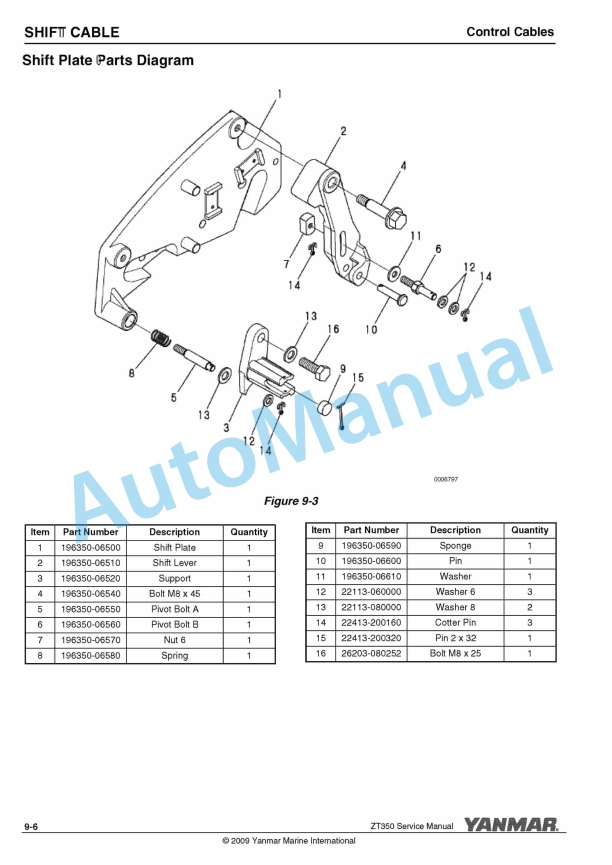
Description
-
Model List:
- ZT350 Stern Drive
- 1. Table of Contents
- 2. Introduction
- 2.1. Revision History
- 2.1.1. Revision Control Table
- 2.2. Safety Precautions
- 3. General Service Information
- 3.1. Responsibilities
- 3.1.1. Owner / Operator Responsibilities
- 3.1.2. Dealer / Distributor Responsibilities
- 3.2. Specifications
- 3.3. Identification
- 3.3.1. Transom Assembly
- 3.3.2. Stern Drive Assembly
- 3.4. Tightening Torques for Standard Bolts and Nuts
- 3.4.1. Tightening Fasteners
- 3.4.2. General Tightening Torque
- 3.4.3. Special Tightening Torques
- 3.4.4. Torque Conversion Chart
- 3.4.5. Hose Clamps
- 3.5. Lubricants, Sealers and Adhesives
- 3.6. Special Service Tools
- 3.7. Abbreviations and Symbols
- 3.7.1. Abbreviations
- 3.7.2. Symbols
- 3.8. Unit Conversions
- 3.8.1. Unit Prefixes
- 3.8.2. Units of Length
- 3.8.3. Units of Volume
- 3.8.4. Units of Mass
- 3.8.5. Units of Force
- 3.8.6. Units of Torque
- 3.8.7. Units of Pressure
- 3.8.8. Units of Power
- 3.8.9. Units of Temperature
- 4. Maintenance
- 4.1. Safety Precautions
- 4.2. Introduction
- 4.3. Checking, Filling and Changing Stern Drive Oil
- 4.3.1. Checking Stern Drive Oil Reservoir Level
- 4.3.2. Checking Stern Drive Oil Level
- 4.3.3. Filling Stern Drive Oil Reservoir
- 4.3.4. Changing Stern Drive Oil
- 4.4. Checking and Filling Power Trim Pump Fluid
- 4.4.1. Checking Power Trim Pump Fluid
- 4.4.2. Filling Power Trim Pump Fluid
- 4.5. Periodic Maintenance
- 4.5.1. The Importance of Periodic Maintenance
- 4.5.2. Performing Periodic Maintenance
- 4.5.3. The Importance of Daily Checks
- 4.5.4. Yanmar Replacement Parts
- 4.5.5. Tools Required
- 4.6. Periodic Maintenance Table
- 4.7. General Inspection
- 4.8. Periodic Maintenance Procedures
- 4.8.1. Checking the Water Inlets
- 4.8.2. Checking the Seawater Inlet Hole
- 4.8.3. Inspecting the Anodes
- 4.8.4. Checking the Oil Level
- 4.8.5. After Initial 50 Hours of Operation
- 4.8.6. Every 50 Hours of Operation
- 4.8.7. Every 100 Hours of Operation
- 4.8.8. Every 250 Hours of Operation
- 4.8.9. Every Year
- 4.9. Cold Weather (Freezing Temperature), Seasonal and Extended Storage
- 4.9.1. Stern Drive Lay-Up
- 4.9.2. Stern Drive Recommissioning
- 5. Stern Drive
- 5.1. Safety Precautions
- 5.2. Introduction
- 5.3. Component Identification
- 5.4. Stern Drive Removal from Transom Assembly
- 5.5. Stern Drive Installation to Transom Assembly
- 5.6. Stern Drive Driveshaft Alignment
- 5.7. Driveshaft Housing and Gear Housing Disassembly
- 5.8. Driveshaft Housing and Gear Housing Assembly
- 6. Driveshaft Housing
- 6.1. Safety Precautions
- 6.2. Introduction
- 6.3. General Views
- 6.4. Driveshaft Housing Part Diagrams
- 6.4.1. Driveshaft Housing and Drive Gear
- 6.4.2. Case Plate and Shifter (Mechanical)
- 6.4.3. Case Plate and Shifter (Electric)
- 6.5. Driveshaft Housing Disassembly
- 6.6. Upper Gear B CMP
- 6.6.1. Disassembly
- 6.6.2. Assembly
- 6.7. Case Plate and Shifter
- 6.7.1. Disassembly – Mechanical Shifter
- 6.7.2. Assembly – Mechanical Shifter
- 6.7.3. Disassembly – Electric Shifter
- 6.7.4. Assembly – Electric Shifter
- 6.7.5. Filter and Magnet Check
- 6.8. Clutch Shaft Set Disassembly and Inspection
- 6.8.1. Ring Retainer Assembly
- 6.9. Driveshaft Housing Assembly
- 6.10. Upper Gear Shim Adjustment
- 6.10.1. Shim Location
- 6.10.2. Determine T1 Shim Thickness – Gear Adjustment B Position
- 6.10.3. Determine T2 Shim Thickness – Gear Adjustment A-1 Position
- 6.10.4. Determine T3 Shim Thickness – Gear Adjustment A-2 Position
- 6.10.5. Determine T4 Shim Thickness – Bearing Clearance Adjustment
- 6.10.6. Setting Gear Backlash
- 7. Gear Housing
- 7.1. Safety Precautions
- 7.2. Introduction
- 7.3. General Views
- 7.4. Gear Housing Part Diagrams
- 7.4.1. Gear Housing Assembly
- 7.5. Disassembly and Inspection
- 7.6. Gear Housing Assembly
- 7.6.1. Driveshaft CMP Assembly
- 8. Transom Assembly
- 8.1. Safety Precautions
- 8.2. Introduction
- 8.3. General Views
- 8.4. Transom Assembly Part Diagrams
- 8.4.1. Gimbal Housing
- 8.4.2. Transom Plate
- 8.5. Gimbal Housing Disassembly
- 8.6. Gimbal Housing Assembly
- 8.7. Tilt-Up Limit Spacer
- 8.8. Speedometer Connection
- 9. Shift Cable
- 9.1. Safety Precautions
- 9.2. Introduction
- 9.3. Control Cables
- 9.3.1. Mechanical Shift Cable Parts Diagram
- 9.3.2. Control Cable Travel
- 9.3.3. Verify Propeller Rotation with Mechanical Shift System
- 9.4. Shift Cable Installation and Adjustment
- 9.4.1. Shift Cable Installation for Electric Shift Type
- 9.4.2. Shift Cable Installation for Mechanical Shift Type
- 9.4.3. Setting the Cable Length
- 9.4.4. Installing the Drive Unit Shift Cable
- 9.4.5. Adjusting the Shift Control Cable
- 9.4.6. Troubleshooting Shift Problems
- 10. Steering
- 10.1. Safety Precautions
- 10.2. Introduction
- 10.3. Power Steering Unit Parts Diagram
- 10.4. Steering Cable Specifications
- 10.5. Installation of Steering Cable
- 10.6. Connecting Steering Cables
- 10.7. Power Steering Unit Installation
- 10.8. Power Steering Hose Installation
- 10.9. Steering Tie Bar Considerations
- 10.9.1. Internal Tie Bar Only
- 10.9.2. Internal and External Tie Bar
- 10.9.3. External Power Steering with an External Tie Bar
- 11. Power Trim System
- 11.1. Safety Precautions
- 11.2. Introduction
- 11.3. Power Trim Pump Parts Diagram
- 11.4. Power Trim Cylinders Parts Diagram
- 11.5. Power Trim System
- 11.6. Power Trim Pump Fluid
- 11.7. Power Trim Cylinders
- 11.8. Power Trim Troubleshooting
- 11.9. Power Trim Pump Installation
- 11.10. Trim Position Sender Connection
- 11.11. Trim-In Limiter
- 12. Propellers
- 12.1. Safety Precautions
- 12.2. Introduction
- 12.3. Propeller Selection
- 12.3.1. Propeller and Propeller Accessory Parts Diagrams
- 12.4. Propeller Installation
- 12.5. Removing Propellers
- 13. Corrosion Protection
- 13.1. Safety Precautions
- 13.2. Introduction
- 13.3. Corrosion Control Parts Diagram
- 13.4. Galvanic Corrosion
- 13.5. Corrosion Control
- 13.6. Shore Power
- 13.7. Underwater Drive Coating
- 13.8. Additional Protection
- 13.9. Gear Housing Anodic Plates
- 13.10. Ventilation Plate Anode
- 13.11. Trim Cylinder Anodes
- 13.12. Propeller Shaft Anode
- 13.13. Yanmar Cathodic Protection System
- 13.14. Corrosion Troubleshooting
- 14. Troubleshooting and Testing
- 14.1. Safety Precautions
- 14.2. Introduction
- 14.3. Stern Drive Unit Troubleshooting
- 14.4. Performance Troubleshooting
- 14.5. Power Steering Troubleshooting
- 14.6. Power Trim System Troubleshooting
- 14.7. Stern Drive Testing
- 14.7.1. Test Preparations
- 14.7.2. Engine Operation Tests
- 14.7.3. Out-of-Water Testing
- 14.7.4. In-Water Testing
- 14.7.5. Wide Open Throttle Test
- 14.7.6. Drive Unit Operational Tests


(C)(M)E%20Service%20Manual&url=https://pdfrepairmanual.com/docs/yanmar-3jh4bcme-service-manual/&media=https://pdfrepairmanual.com/wp-content/uploads/2026/01/yanmar-3jh4bcme-service-manual-1.jpg)
There are no reviews yet.