
Description
-
Model List:
- HD325-8E0 Dump Truck
- HD405-8E0 Dump Truck
- 1. COVER
- 2. Contents
- 3. Outline of separation (only for main components)
- 4. Dimensions of main components, Sales code 7HC16
- 5. Dimensions of main components, Sales code 7HC61
- 6. Dimensions of main components, Sales code 7HC62
- 7. Rough schedule of assembling and welding (for normal disassembly packing)
- 8. Layout of work space
- 9. Facility, jig and consumable parts list
- 10. Field assembly procedure
- 10.1. Oil, grease and coolant
- 10.2. Amount of oil, grease and coolant
- 10.3. Installation of tire and wheel assembly (front)
- 10.4. Installation of rear tires and wheel assembly HD325
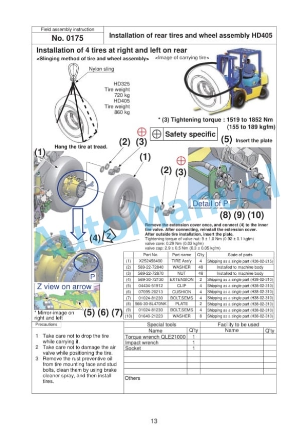
- 10.5. Installation of rear tires and wheel assembly HD405
- 10.6. Installation of exhaust TUBE on R.H. platform
- 10.7. Installation of exhaust TUBE on R.H. platform Dump body heatingless
- 10.8. Installation of R.H. side mirror
- 10.9. Installation of R.H. platform mudguard HD325
- 10.10. Installation of R.H. platform mudguard HD405
- 10.11. Installation of R.H. platform antenna pole
- 10.12. Installation of R.H. platform antenna
- 10.13. Installation of R.H. platform antenna harness for KOMTRAX5
- 10.14. Installation of R.H. platform antenna harness for KOMTRAX iridium
- 10.15. Installation of bumper step
- 10.16. Installation of front under mirror
- 10.17. Installation of wheel chocks
- 10.18. Installation of L.H. catwalk mount
- 10.19. Installation of CAB rear handrail
- 10.20. Installation of L.H. catwalk assembly
- 10.21. Fixing and connection of L.H. catwalk harness
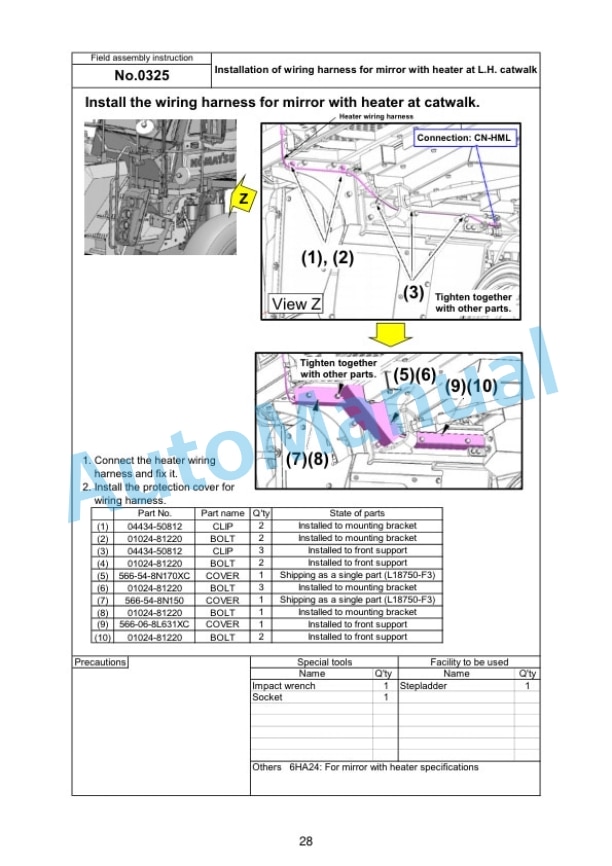
- 10.22. Installation of wiring harness for mirror with heater at L.H. catwalk
- 10.23. Installation of L.H. catwalk harness cover
- 10.24. Connection of PLM harness
- 10.25. Installation of fender mudguard
- 10.26. Mounting of dump body
- 10.27. Removal of hoist cylinder fixing jig
- 10.28. Installation and shim adjustment of dump body pad
- 10.29. Shim adjustment of dump body securing pad
- 10.30. Welding of exhaust pipe tube by actually positioning parts on machine
- 10.31. Installation of dump body mudguard HD325
- 10.32. Installation of dump body mudguard HD405
- 10.33. Installation of dump body rock ejector and lock pin
- 10.34. Connection and adjustment of dump angle sensor
- 10.35. Dump body control calibration
- 10.36. Air bleeding of hoist cylinder
- 10.37. Sticking of dump body decal HD325
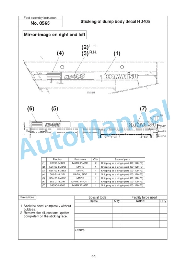
- 10.38. Sticking of dump body decal HD405
- 10.39. Sticking of tieoff decals to dump for compliance withAustralian regulations
- 10.40. Adjustment of mirror angle 1/2
- 10.41. Adjustment of mirror angle 2/2
- 10.42. Check and adding of each oil, etc.
- 10.43. Adjustment of suspension gas
- 10.44. C0010 Preparation of dump body welding
- 10.45. C0020 Assembly work of dump body
- 10.46. C0030 Tack welding of dump body
- 10.47. C0040 Dump body welding
- 10.48. C0050 Dump body welding procedure 1
- 10.49. C0060 Dump body welding procedure 2
- 10.50. C0070 Dump body welding procedure 3
- 10.51. C0080 Dump body welding procedure 4
- 10.52. C0090 Turning over of dump body
- 10.53. C0100 Welding of dump body protector
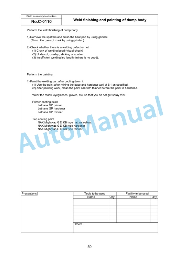
- 10.54. C0110 Weld finishing and painting of dump body
- 10.55. C0120 Welding of dump body protector
- 10.56. B010 Installation of subassembly of the dump body CAB guard
- 10.57. B020 Installation of subassembly of the dump body platform guard 6HM57T
- 10.58. B030 Installation of subassembly of the dump body 150 CM spill guard
- 11. Appendix Machine check sheet for field assembly


Reviews
There are no reviews yet.