
Description
-
Model List:
- HD465-7E0 Dump Truck
- HD605-7E0 Dump Truck
- 1. COVER
- 2. CONTENTS
- 3. Major points changed from model 7
- 4. Outline of division
- 5. Dimensions of main components
- 6. Rough schedule of assembly and welding
- 7. List of equipments, tools, and consumables
- 8. Assembly process No.
- 8.1. List of jigs, tools, and consumables
- 8.2. Oil, grease, and coolant
- 8.3. Levels of oil, grease, and coolant
- 8.4. Positioning rear axle assembly
- 8.5. Installing rear suspension
- 8.6. Installing of axle rod (upper)
- 8.7. Slinging bare machine
- 8.8. Installing rear axle assembly (Connecting axle rods)
- 8.9. Connecting rear suspension
- 8.10. Positioning bare machine
- 8.11. Installing right front axle (Connecting Aarm)
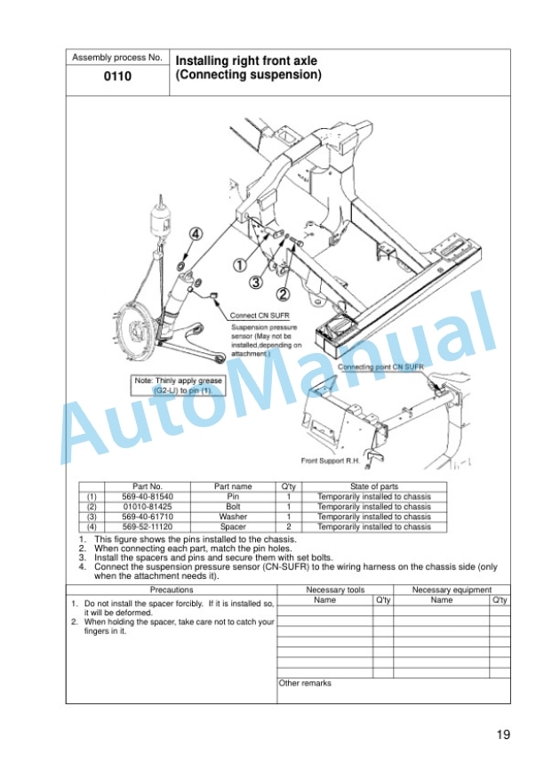
- 8.12. Installing right front axle (Connecting suspension)
- 8.13. Installing right front axle (Connecting steering cylinder and tie rod)
- 8.14. Installing right front axle (Connecting brake hose)
- 8.15. Installing right front axle (Connecting piping for automatic suspension)
- 8.16. Connection and fixing of right front axle wiring harness (ABS specification)
- 8.17. Installing tire and wheel assembly
- 8.18. Installing body hinge grease tube
- 8.19. Installation of rear monitor
- 8.20. Installing drive shaft
- 8.21. Connecting cooling hose
- 8.22. Connecting brake actuating hose
- 8.23. Connection and fixing of rear centralized lubrication hoses 4point greasing
- 8.24. Installing right front support
- 8.25. Installing R.H platform assembly
- 8.26. Fixing of ORBCOMM antenna cable
- 8.27. Installation of ORBCOMM antennal pole
- 8.28. Installing of fire prevention cover
- 8.29. Installation of fire prevention cover (Sand terrain specification)
- 8.30. Installing right fender
- 8.31. Installation of right fender (Side lamp specification)
- 8.32. Installing L.H catwalk assembly
- 8.33. Installing L.H handrail
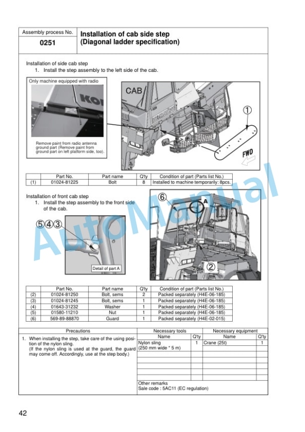
- 8.34. Installation of cab side step (Diagonal ladder specification)
- 8.35. Installation of diagonal ladder 1 (Diagonal ladder specification)
- 8.36. Installation of diagonal ladder 2 (Diagonal ladder specification)
- 8.37. Installation of diagonal ladder 3 (Diagonal ladder specification)
- 8.38. Assembly of diagonal ladder (Diagonal ladder specification)
- 8.39. Installation of under view mirror (Diagonal ladder specification)
- 8.40. Installing radio antenna and fixing its cable
- 8.41. Installing L.H fender
- 8.42. Installation of left fender (Side lamp specification)
- 8.43. Installing left side mudguard
- 8.44. Installing right side mudguard
- 8.45. Installation of R.H exhaust pipe cover (Muffler specification)
- 8.46. Installation of R.H exhaust pipe cover (Exhaust selector box specification)
- 8.47. Installing transmission underguard
- 8.48. Installation of radiator curtain (Radiator curtain specification and sand terrain specification)
- 8.49. Removing hoist cylinder bracket
- 8.50. Removing hoist piping blind plate
- 8.51. Welding body
- 8.52. Slinging body
- 8.53. Installing hinge pin
- 8.54. Connecting hoist cylinder
- 8.55. Welding protective cover by actually positioning it on machine
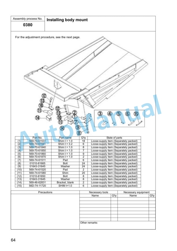
- 8.56. Installing body mount
- 8.57. Procedure for adjusting body mount shim
- 8.58. Welding front body mount bracket
- 8.59. Welding exhaust tube by actually positioning it on machine
- 8.60. Installation of grease junction tube 4point greasing specification
- 8.61. Installing poke ejector
- 8.62. Installing body lock pin
- 8.63. Installing body mudguard
- 8.64. Connecting dump sensor
- 8.65. Procedure for adjusting dump sensor
- 8.66. Calibrating dump control
- 8.67. Bleeding air from brake system (Preparation)
- 8.68. Bleeding air from brake system (Front)
- 8.69. Bleeding air from brake system (Rear)
- 8.70. Adjusting suspension
- 8.71. Greasing (Right front axle)
- 8.72. Greasing (Hoist cylinder)
- 8.73. Greasing (Rear suspension and axle rod)
- 8.74. Painting
- 8.75. Sticking body decal
- 8.76. Removing jig
- 8.77. Adjusting angles of mirrors
- 8.78. Checking/Adding lubricants
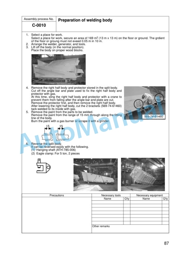
- 8.79. C0010 Preparation of welding body
- 8.80. C0020 Assembly of split body
- 8.81. C0030 Tack welding body
- 8.82. C0040 Welding body
- 8.83. C0050 Welding body instruction (1/2)
- 8.84. C0060 Welding body instruction (2/2)
- 8.85. C0070 Turn over the body
- 8.86. C0080 Welding body protector (1/2)
- 8.87. C0090 Welding body protector (2/2)
- 8.88. C0100 Finishing and painting welded parts of body
- 8.89. C0110 Reworking on body (Exhaust selector box specification)
- 8.90. C0120 Welding of body exhaust pipe (Exhaust selector box specification)
- 9. Appendix Field assembly inspection report


Reviews
There are no reviews yet.