

Description
-
Model List:
- PC1250-8R Hydraulic Excavator
- PC1250SP-8R Hydraulic Excavator
- 1. Cover
- 2. FOREWARD
- 3. CONTENTS
- 4. Specifications
- 5. Precautions for Field Assembly
- 6. Assembling Procedures, Applicable Equipment and Schedule
- 7. Kit Layout Diagram
- 8. Transportation
- 9. List of Tools for Field Assembling
- 10. Tightening Torque
- 11. Coating Materials
- 12. List of parts sent individually
- 13. Assembly of Chassis
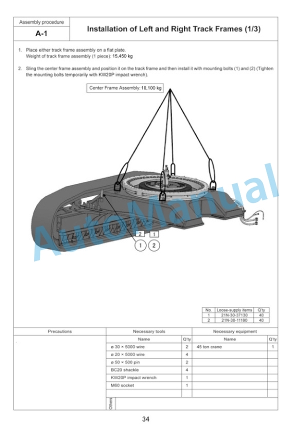
- 13.1. A1. Installation of Left and Right Track Frames
- 13.2. A2. Installation of Travel Piping
- 13.3. A3. Installation of Travel Piping Covers
- 13.4. A4. Installation of Steps
- 13.5. A5. Filling Swing Circle with Grease
- 13.6. A6. Assembly of Upper Structure and Undercarriage
- 13.7. A7. Installation of Right Side Steps
- 13.8. A8. Installation of Handrails
- 13.9. A9. Installation of Swivel Travel Piping
- 13.10. A10. Installation of Cover board (To the Counterweight)
- 13.11. A11. Installation of Counterweight
- 13.12. A12. Installation of Left Side Steps (Including handrails)
- 13.13. A13. Installation of Radiator Cover (Standard specification)
- 13.14. A14. Installation of Muffler Tail Pipe
- 13.15. A15. Changing of Mounting Position of Step Light
- 13.16. A16. Installation of Handrail to the Cab
- 13.17. A17. Installation of Left Rearview Mirror
- 13.18. A18. Installation of Right Rearview Mirrors
- 13.19. A19. Preparation for Bleeding Air from Travel Motor
- 13.20. A20. Procedure for Bleeding Air From Hydraulic Circuit
- 13.21. A21. Permanent Tightening of Swing Circle Mounting Bolts
- 13.22. A22. Testing Track Shoe Tension
- 13.23. A23. Check Fuel, Coolant and Oil Levels
- 13.24. A24. Parts to be Touched up after Field Assembly
- 14. Assembling of Work Equipment of Backhoe
- 14.1. B1. Installation of Arm Cylinder
- 14.2. B2. Installation of Arm Cylinder Hoses
- 14.3. B3. Installation of Boom Cylinder Foot
- 14.4. B4. Installation of Boom Cylinder Hoses
- 14.5. B5. Installation of Boom Foot Dust Seal
- 14.6. B6. Installation of Boom Assembly
- 14.7. B7. Installation of Boom Cylinder
- 14.8. B8. Installation of Boom Hoses (Between machine and boom)
- 14.9. B9. Installation of Arm Assembly
- 14.10. B10. Installation of Bucket Cylinder Hoses between Boom and Bucket Cylinder
- 14.11. B11. Installation of Bucket Assembly
- 14.12. B12. Clearance Standard for Installation of Work Equipment
- 14.13. B13. Installation of Work Equipment Grease Piping
- 14.14. B14. Procedure for Bleeding Air From Travel Motor
- 14.15. B15. Bleeding Air from Swing Motor
- 14.16. B16. Bleeding Air from Cylinder
- 14.17. B17. Installation of Work Equipment Wiring
- 14.18. B18. Greasing after Assembling Work Equipment
- 15. Procedure for Inspection and Maintenance after Completion of Assembly
- 15.1. M1. Replacement of Return Filter (Standard Filter to Flushing Filter)
- 15.2. M2. Relieving Remaining Pressure from Hydraulic Circuit
- 15.3. M3. Installation of Flushing Tubes
- 15.4. M4. Flushing of Hydraulic Circuit
- 15.5. M5. Replacement of Pilot Filter (Flushing filter to Standard filter)
- 16. Procedure for assembling work equipment of loading shovel
- 16.1. Transportation posture (only work equipment)
- 16.2. List of parts sent individually
- 16.3. C1. Installation of Arm Cylinder Bottoms
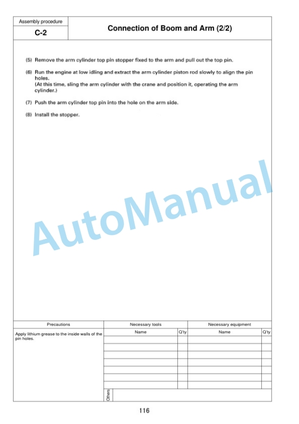
- 16.4. C2. Connection of Boom and Arm
- 16.5. C3. Pulling out Boom Foot Pin and Boom Cylinder Foot Pin
- 16.6. C4. Installation of Boom and Arm Assembly
- 16.7. C5. Replacement of Return Filter (Standard Element Flushing Element)
- 16.8. C6. Releasing Residual Pressure in Hydraulic Circuit
- 16.9. C7. Installation of Boom Hoses (Between Chassis and Boom)
- 16.10. C8. Installation of Flushing Tube for Boom Cylinder Hoses
- 16.11. C9. Installation of Flushing Tube for Arm Cylinder Hoses
- 16.12. C10. Installation of Flushing Tube for Bucket Cylinder Hoses
- 16.13. C11. Installation of Hoses Between Boom and Arm (Bottom Dump)
- 16.14. C12. Installation of Flushing Tube for Bottom Dump Cylinder Hoses
- 16.15. C13. Installation of Hydraulic Circuit
- 16.16. C14. Replacement of Pilot Filter (Flushing Element Standard Element)
- 16.17. C15. Installation of Boom Cylinder Bottoms
- 16.18. C16. Installation of Boom Cylinder Hoses
- 16.19. C17. Installation of Boom Cylinder Head Pin
- 16.20. C18. Installation of Arm Cylinder Hoses
- 16.21. C19. Installation of Bucket Cylinder
- 16.22. C20. Installation of Bucket Cylinder Hoses
- 16.23. C21. Installation of Bucket Assembly
- 16.24. C22. Installation of Bottom Dump Cylinder Hoses
- 16.25. C23. Maintenance Standard
- 16.26. C24. Installation of Working Lamp
- 16.27. C25. Installation of Work Equipment Greasing Piping
- 16.28. C26. Bleeding Air from Work Equipment Circuit
- 16.29. C27. Checking Oil Level in Hydraulic Tank and Adding Oil
- 16.30. C28. Greasing After Assembling Work Equipment
- 16.31. Inspection of each part after assembly of loader
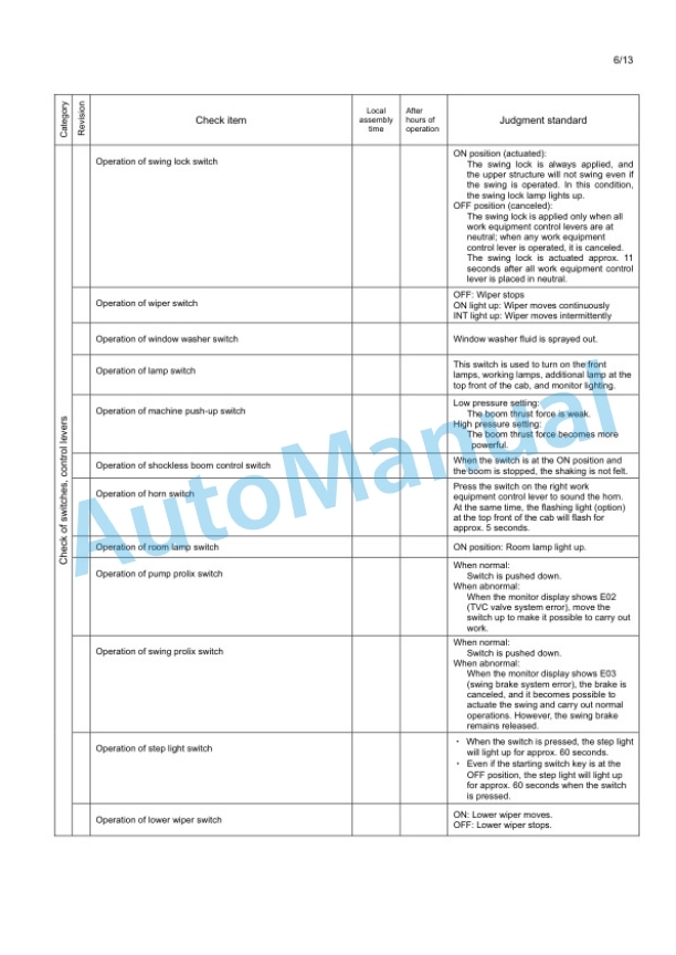
- 17. Field Assembly Inspection Report (Backhoe)
- 18. Field Assembly Inspection Report (Loading shovel)







Reviews
There are no reviews yet.