
Description
-
Model List:
- PC500LC-10M0 Hydraulic Excavator
- PC500LC-10R Hydraulic Excavator
- 1. COVER
- 2. FOREWORD
- 3. CONTENTS
- 4. Specifications
- 5. Precautions for Field Assembly
- 6. Disposal of removed parts
- 7. Assembling procedures,applicable equipment and schedule
- 8. Flow of field assembly
- 9. Kit layout diagram
- 10. Transportation
- 11. Tool list for field assembly
- 12. Tightening torque
- 13. Coating materials
- 14. Selection of wire ropes used for assembly
- 15. Selection of nylon slings used for assembly
- 16. Assembly of Chassis
- 16.1. A1. Installation of steps
- 16.2. A2. Installation of climbing grip
- 16.3. A3. Installation of handrail (if equipped)
- 16.4. A4. Installation of mirror
- 17. Assembling of Work Equipment
- 17.1. B1. Installation of boom cylinder
- 17.2. B2. Releasing remaining pressure in hydraulic circuit
- 17.3. B3. Installation of boom cylinder hoses
- 17.4. B4. Installation of boom cylinder top pin
- 17.5. B5. Installation of boom assembly
- 17.6. B6. Installation of hoses from chassis along top of boom
- 17.7. B7. Connection of boom cylinder head
- 17.8. B8. Installation of arm assembly
- 17.9. B9. Installation of bucket cylinder hoses between boom and bucket cylinder
- 17.10. B10.Installation of bucket assembly
- 17.11. B11. Connection of work equipment grease piping
- 17.12. B12. Connection of work equipment wiring
- 17.13. B13. Installation of LED working lamps (if equipped)
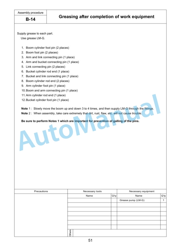
- 17.14. B14. Greasing after completion of work equipment
- 17.15. B15.Bleeding air from work equipment hyd. circuit
- 18. Assembling of counterweight and adjustment
- 18.1. C1. Adjustment of track tension
- 18.2. C2. Sticking sheet to revolving frame
- 18.3. C3. Sticking sheet to counterweight
- 18.4. C4. Installation of rear view mirror
- 18.5. C5. Installation of camera (if equipped)
- 18.6. C6. Installation of counterweight
- 19. Procedure for Inspection and Maintenance after Completion of Assembly
- 19.1. M1. Replacement of return filter (Standard filter to flushing filter)
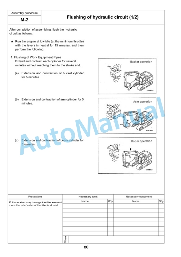
- 19.2. M2. Flushing of hydraulic circuit
- 19.3. M3. Replacement of return filter (Flushing filter to standard filter)
- 19.4. M4. Check of oil/coolant level at each part
- 19.5. M5. Inspection of oil level in hydraulic tank and refill
- 19.6. M6. Parts to be touched up after field assembly
- 19.7. M7. Adjust KomVision Camera angle (KomVision Spec.)(Camera calibration and12 m visibility check)
- 19.8. M8. Error code
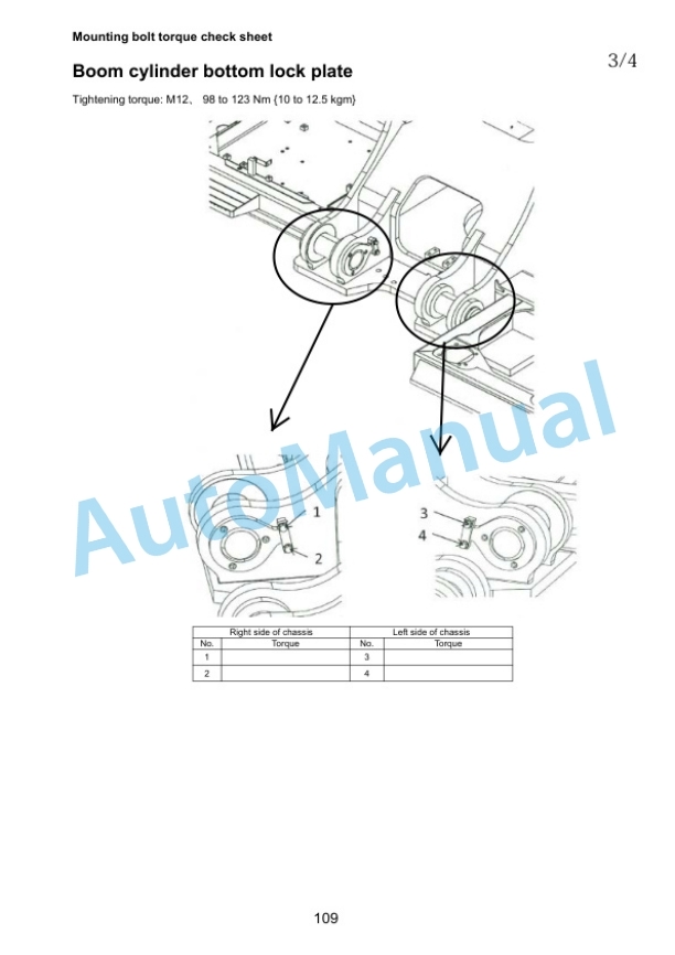
- 20. Mounting bolt torque check sheet
- 21. FIELD ASSEMBLY INSPECTION REPORT


Reviews
There are no reviews yet.