Hyster 2.6L, 3.0L, 3.3L Yanmar Diesel Engines Maintenance And Repair
$30.00
- Type Of Manual: Maintenance And Repair
- Number of Pages: 1050
- Size: 50.0MB
- Format: PDF
Description
-
Model List:
- 2.6L, 3.0L, 3.3L Yanmar Diesel Engines
- 1. RM1205-(09-2021)-UK-EN
- 1.1. General
- 1.1.1. Engine Identification
- 1.2. Engine Removal and Installation
- 1.3. Cylinder Head Assembly Repair
- 1.3.1. Glow Plugs
- 1.3.2. Install
- 1.3.3. Valve Cover
- 1.3.4. Rocker Arm Assembly
- 1.3.5. Valve Clearance Adjustments
- 1.3.6. Cylinder Head Assembly
- 1.4. Timing Gear Case and Timing Gears Repair
- 1.4.1. Timing Gear Case Cover
- 1.4.2. Timing Gears
- 1.4.3. Timing Gear Case
- 1.5. Drive Train, Camshaft, and Cylinder Block Repair
- 1.5.1. Disassemble
- 1.5.2. Clean and Inspect
- 1.5.3. Assemble
- 1.5.4. Install
- 1.6. Lubrication System Repair
- 1.6.1. Engine Oil and Oil Filter Change
- 1.6.2. Oil Pan
- 1.6.3. Oil Suction Tube
- 1.6.4. Oil Pump
- 1.7. Fuel System Repair
- 1.7.1. Fuel Injectors
- 1.7.2. Inspect
- 1.7.3. Electronic Throttle System
- 1.7.4. Manual Throttle System
- 1.7.5. Fuel Injection Pump
- 1.8. Cooling System Repair
- 1.8.1. Water Pump
- 1.8.2. Thermostat
- 1.9. Flywheel and Flywheel Housing
- 1.9.1. Flywheel
- 1.9.2. Flywheel Housing
- 1.10. Electrical Equipment Repair
- 1.10.1. Alternator
- 1.10.2. Starter
- 1.11. Engine Specifications
- 1.11.1. Engine Data
- 1.11.2. Engine Tuning
- 1.11.3. Cylinder Head
- 1.11.4. Intake/Exhaust Valve and Guide
- 1.11.5. Valve Spring
- 1.11.6. Rocker Arm and Shaft
- 1.11.7. Push Rod
- 1.11.8. Gear Train and Camshaft
- 1.11.9. Cylinder Block
- 1.11.10. Crankshaft
- 1.11.11. Thrust Bearing
- 1.11.12. Piston Ring
- 1.11.13. Connecting Rod
- 1.11.14. Oil Pump
- 1.12. Standard Torque Specifications
- 1.12.1. Standard Torque Chart
- 1.13. Special Torque Specifications
- 1.14. Special Tools
- 2. RM1755-(01-2022)-UK-EN
- 2.1. General
- 2.2. Engine Removal and Installation
- 2.3. Cylinder Head Assembly Repair
- 2.4. Drive Train and Lubrication System
- 2.4.1. Disassemble
- 2.4.2. Oil Pan
- 2.4.3. Oil Pump (Front Cover)
- 2.4.4. Clean and Inspect
- 2.4.5. Assemble
- 2.4.6. Install
- 2.5. Crankshaft and Cylinder Block Repair
- 2.5.1. Remove Major Attaching Components
- 2.5.2. Crankshaft and Cylinder Block
- 2.5.3. Piston and Connecting Rod
- 2.5.4. Install Major Attaching Components
- 2.6. Fuel System Repair
- 2.7. Cooling System Repair
- 2.8. Electrical Equipment Repair
- 2.9. Flywheel and Flywheel Housing
- 2.9.1. Flywheel
- 2.9.2. Flywheel Housing
- 2.10. POWER TAKE OFF (PTO), REMOVE AND INSTALL
- 2.10.1. REMOVE COVER
- 2.10.2. INSTALL COVER
- 2.11. Engine Specifications
- 2.11.1. Engine Data
- 2.11.2. Engine Tuning
- 2.11.3. Cylinder Head
- 2.11.4. Intake/Exhaust Valve and Guide
- 2.11.5. Valve Spring
- 2.11.6. Gear Train and Camshaft
- 2.11.7. Cylinder Block
- 2.11.8. Crankshaft
- 2.11.9. Piston Ring
- 2.11.10. Connecting Rod
- 2.11.11. Oil Pump
- 2.12. Torque Specifications
- 2.13. Special Tools
- 3. RM1921-(09-2021)-UK-EN
- 3.1. General
- 3.1.1. Engine Identification
- 3.2. Engine Removal and Installation
- 3.3. Cylinder Head Assembly Repair
- 3.3.1. Valve Covers and Fuel Injectors
- 3.3.2. Rocker Arm Assembly
- 3.3.3. Valve Clearance Adjustments
- 3.3.4. Compression Test
- 3.3.5. Cylinder Head Assembly
- 3.4. Timing Gear Case and Timing Gears Repair
- 3.4.1. Timing Gear Case Cover
- 3.4.2. Timing Gears
- 3.5. Drive Train, Camshaft, and Cylinder Block Repair
- 3.5.1. Disassemble
- 3.5.2. Clean and Inspect
- 3.5.3. Assemble
- 3.5.4. Install
- 3.6. Lubrication System Repair
- 3.6.1. Engine Oil and Oil Filter Change
- 3.6.2. Oil Pan
- 3.6.3. Oil Suction Tube
- 3.6.4. Oil Pump
- 3.7. Fuel System Repair
- 3.7.1. Fuel Injectors
- 3.7.2. Fuel Injection Pump/Supply Pump
- 3.8. Cooling System Repair
- 3.8.1. Accessory Drive Belt
- 3.8.2. Water Pump
- 3.8.3. Thermostat
- 3.9. Flywheel and Flywheel Housing
- 3.9.1. Flywheel
- 3.9.2. Flywheel Housing
- 3.10. Electrical Equipment Repair
- 3.10.1. Alternator
- 3.10.2. Starter
- 3.11. Engine Specifications
- 3.11.1. Engine Data
- 3.11.2. Engine Tuning
- 3.11.3. Cylinder Head
- 3.11.4. Intake/Exhaust Valve and Guide
- 3.11.5. Valve Spring
- 3.11.6. Rocker Arm and Shaft
- 3.11.7. Push Rod
- 3.11.8. Gear Train and Camshaft
- 3.11.9. Cylinder Block
- 3.11.10. Crankshaft
- 3.11.11. Piston Ring
- 3.11.12. Connecting Rod
- 3.11.13. Oil Pump
- 3.12. Standard Torque Specifications
- 3.12.1. Standard Torque Chart
- 3.13. Special Torque Specifications
- 3.14. Special Tools
- 4. RM2199-(04-2022)-UK-EN
- 4.1. Forklift Truck Main Parts
- 4.1.1. Description of Forklift Truck Main Parts
- 4.2. Forklift Main Technical Parameters
- 4.2.1. Main Technical Parameters
- 4.3. Power System
- 4.3.1. Engine System
- 4.4. Hydraulic Transmission Case and Torque Converter
- 4.4.1. Overview
- 4.4.2. Torque Converter
- 4.4.3. Hydraulic Clutch
- 4.4.4. Control Valve, Safety Valve, and Inching Valve
- 4.4.5. Transmission Case
- 4.4.6. Transmission Pump
- 4.4.7. Transmission hydraulic schematic
- 4.4.8. Speed Reducer and Speed Differential
- 4.4.9. Towing the Lift Truck
- 4.4.10. Oil Inlet/Outlet Connection Location
- 4.5. Drive Axle
- 4.5.1. Overview
- 4.5.2. Maintenance of Drive Axle
- 4.6. Steering System
- 4.6.1. Steering System
- 4.7. Steering and Drive Axle Information
- 4.7.1. Steering Axle
- 4.8. Brake System
- 4.8.1. Overview
- 4.8.2. Brake Master Cylinder
- 4.8.3. Wheel Brake
- 4.8.4. Automatic Brake Adjuster
- 4.8.5. Manual Brake
- 4.8.6. Adjustment of Brake Pedal
- 4.8.7. Maintenance
- 4.9. Hydraulic System
- 4.9.1. Overview
- 4.9.2. Steering Control Unit
- 4.9.3. Multi-way Valve and Priority spool
- 4.9.4. Hydraulic System Main Oil Circuit
- 4.9.5. Lift Cylinder
- 4.9.6. Velocity Fuse
- 4.9.7. Tilt Cylinder
- 4.9.8. Maintenance of Hydraulic Pump
- 4.9.9. Troubleshoot Hydraulic System
- 4.10. Lifting System
- 4.10.1. Safety Procedures When Working Near Mast
- 4.10.2. Overview
- 4.10.3. Inside and Outside Masts
- 4.10.4. Carriage
- 4.10.5. Adjustment of Lifting System
- 4.11. Electrical System
- 4.11.1. Overview
- 4.11.2. Electrical Box
- 4.11.3. Battery
- 4.11.4. Description and Summary of Basic Truck Operations
- 4.11.5. Introduction to the Power Distribution Module (PDM)
- 4.11.6. Electrical Schematics
- 4.11.7. Troubleshoot Electrical System
- 4.12. Drive, Operation, and Routine Maintenance of Forklift Truck
- 4.12.1. Cooling System Troubleshooting and Service
- 4.12.2. Oils Used for Forklift Truck
- 4.12.3. Hydraulic Oil Gauge and Hydraulic Oil fill
- 4.12.4. Lubrication System
- 4.13. PDM Schematics
- 5. RM2415-(02-2022)-UK-EN
- 5.1. General
- 5.2. Description
- 5.3. Hood, Seat, and Side Covers Replacement
- 5.3.1. Disassemble
- 5.3.2. Re-assemble
- 5.4. Steering Column
- 5.4.1. Description
- 5.4.2. Steering Column Repair
- 5.5. Counterweight Replacement
- 5.5.1. Install
- 5.6. Overhead Guard Replacement
- 5.6.1. Remove and Install
- 5.7. Operator Restraint System Replacement
- 5.7.1. Description
- 5.8. Engine and Transmission Replacement
- 5.8.1. Engine and Transmission Disassembly
- 5.9. Exhaust System Repair
- 5.9.1. Remove and Re-assemble
- 5.9.2. Inspect
- 5.10. Cooling System
- 5.10.1. Description
- 5.11. Hydraulic Filter Assembly Repair
- 5.11.1. Disassemble
- 5.11.2. Clean and Inspect
- 5.11.3. Re-assemble
- 5.12. Fuel and Hydraulic Tanks Repair
- 5.12.1. Inspect
- 5.12.2. Additional Preparations for Repair
- 5.12.3. Small Leaks, Repair
- 5.12.4. Large Leaks, Repair
- 5.12.5. Preparations for Use After Repair
- 5.13. Safety Labels
- 6. RM2413-(02-2022)-UK-EN
- 6.1. General
- 6.2. Cooling System Checks
- 6.2.1. Exhaust Leaks Into Cooling System
- 6.2.2. Water Flow Restrictions in Radiator
- 6.2.3. Radiator Hoses
- 6.2.4. Water Pump
- 6.3. Flushing the Cooling System
- 6.3.1. Cooling System, Clean
- 6.4. Radiator Replacement
- 6.4.1. Radiator, Remove
- 6.4.2. Radiator, Install
- 6.5. Fan Assembly Replacement
- 6.5.1. Fan Removal
- 6.5.2. Inspect
- 6.5.3. Fan Installation
- 7. RM2416-(10-2022)-UK-EN
- 7.1. General
- 7.2. Intake-Air System
- 7.2.1. Intake-Air System Manifold Vacuum Check
- 7.2.2. Throttle Body
- 7.2.3. Intake Manifold
- 7.3. LPG Tank and Bracket Replacement with Swing-Out Bracket
- 7.3.1. Remove LPG Tank
- 7.3.2. Install LPG Tank
- 7.3.3. Remove LPG Bracket
- 7.3.4. Install LPG Bracket
- 7.4. Fuel Filter and Fuel Level Sensor Repair
- 7.4.1. FUEL FILTER ELEMENT
- 7.4.2. Fuel Level Sensor
- 7.5. Electronic Throttle Body Repair
- 7.5.1. Install
- 7.6. LPG Fuel Mixer With Direct Electronic Pressure Regulator (DEPR) Repair
- 7.6.1. Install
- 7.7. Control System
- 7.7.1. Engine Control Module (ECM)
- 7.8. LPG Converter
- 7.9. LPG Lock-Off Valve
- 7.9.1. Install
- 7.10. Exhaust System
- 7.10.1. Counterweight Exhaust System
- 7.10.2. Oxygen Sensor
- 8. RM2419-(07-2021)-UK-EN
- 8.1. GENERAL
- 8.2. TRANSMISSION
- 8.2.1. CLEAN AND INSPECT
- 8.2.2. INSTALL
- 8.3. PEDAL REPAIR
- 8.3.1. REMOVE AND DISASSEMBLE
- 8.3.2. CLEAN AND INSPECT
- 8.3.3. ASSEMBLE AND INSTALL
- 9. RM2409-(02-2022)-UK-EN
- 9.1. General
- 9.2. Drive Axle Repair
- 9.2.1. Remove and Disassemble
- 9.2.2. Clean and Inspect
- 9.2.3. Re-assemble and Install
- 10. RM2410-(07-2021)-UK-EN
- 10.1. General
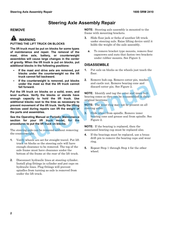
- 10.2. Steering Axle Assembly Repair
- 10.2.1. Disassemble
- 10.2.2. Inspect
- 10.2.3. Re-assemble
- 10.2.4. Install
- 10.3. Spindles, Bearings, and Tie Rods Repair
- 10.3.1. Remove and Disassemble
- 10.3.2. Inspect
- 10.3.3. Install and Assemble
- 10.4. Steering Cylinder Repair
- 10.4.1. Remove and Disassemble
- 10.4.2. Clean and Inspect
- 10.4.3. Assemble and Install
- 11. RM2411-(07-2021)-UK-EN
- 11.1. GENERAL
- 11.2. SERVICE BRAKE REPAIR
- 11.2.1. REMOVE AND DISASSEMBLE
- 11.2.2. INSPECT
- 11.2.3. ASSEMBLE AND INSTALL
- 11.3. PARKING BRAKE REPAIR
- 11.3.1. REMOVE AND DISASSEMBLE
- 11.3.2. ASSEMBLE AND INSTALL
- 11.4. MASTER CYLINDER REPAIR
- 11.4.1. DISASSEMBLE
- 11.4.2. CLEAN AND INSPECT
- 11.4.3. ASSEMBLE
- 11.4.4. BENCH BLEED MASTER CYLINDER
- 11.4.5. INSTALL
- 11.4.6. SERVICE BRAKE ADJUSTMENT
- 11.4.7. SERVICE BRAKE AIR REMOVAL
- 12. RM2417-(10-2022)-UK-EN
- 12.1. Cylinder
- 12.1.1. General
- 12.1.2. Safety Procedures When Working Near Mast
- 12.1.3. Integral Sideshift Cylinder Repair
- 12.1.4. Free-Lift Cylinder
- 12.1.5. Main Lift Cylinder Repair
- 12.1.6. Tilt Cylinder Repair
- 12.2. Hydraulic Gear Pump
- 12.2.1. General
- 12.2.2. Hydraulic Gear Pump Repair
- 12.3. Main Control Valve
- 12.3.1. General
- 12.3.2. Main Control Valve
- 13. RM2414-(10-2022)-UK-EN
- 13.1. General
- 13.2. Combination Switch
- 13.2.1. Remove and Install
- 13.3. Display and Rocker Switch
- 13.3.1. Remove and Install
- 13.4. Battery and Power Distribution Module
- 13.4.1. Remove and Install
- 13.5. Auxiliary Relay and Fuse Box
- 13.5.1. Remove and Install
- 13.6. Sensors and Switches
- 13.6.1. General
- 13.6.2. Accelerator Pedal Position Sensor
- 13.6.3. Parking Brake Sensor
- 13.6.4. Fuel Level Sensor
- 13.6.5. Torque Converter Temperature Sensor
- 13.6.6. Engine Coolant Temperature Sensor
- 13.6.7. CAM Sensor
- 13.6.8. Crank Sensor
- 13.6.9. Map Sensor
- 13.6.10. Oil Pressure Sensor
- 13.6.11. Oxygen Sensors
- 13.6.12. Fuel Shut-off Valve, Fuel filter, Fuel Pump, and Fuel Temperature Sensor
- 13.6.13. Remove and Install
- 13.7. Main Harness and OPS Harness
- 14. RM2418-(04-2022)-UK-EN
- 14.1. General
- 14.2. Safety Procedures When Working Near Mast
- 14.3. Fork Replacement
- 14.3.1. Standard Carriage and Integral Sideshift Carriage
- 14.4. Carriages Repair, Three-Stage FFL Mast
- 14.4.1. Standard Carriage
- 14.4.2. Integral Sideshift Carriage
- 14.5. Three-Stage Mast With Full Free-Lift Repair
- 14.5.1. Disassemble and Re-assemble
- 14.5.2. Clean and Inspect
- 14.6. Carriage Adjustments
- 14.7. Lift Chains Adjustment
- 14.8. Mast Adjustments
- 14.8.1. Load Roller, Adjust
- 14.8.2. Mast Side Kicking, Adjust
- 15. RM2407-(10-2022)-UK-EN
- 15.1. Electrical Schematics
- 15.2. Hydraulic Schematics
- 15.3. Operator Presence System (OPS) Schematic
- 15.4. Power Distribution Module (PDM) Schematics
- 16. RM2408-(10-2022)-UK-EN
- 16.1. General
- 16.1.1. How to Move a Disabled Lift Truck
- 16.1.2. How to Put a Lift Truck on Blocks
- 16.1.3. HOW TO CLEAN A LIFT TRUCK
- 16.2. Maintenance Schedule
- 16.3. Maintenance Procedures Every 8 Hours or Daily
- 16.3.1. How to Make Checks With Engine Stopped
- 16.3.2. How to Make Checks With Engine Running
- 16.4. Maintenance Procedures Every 250 Hours or 4 Months



%20Service%20Manual&url=https://pdfrepairmanual.com/docs/hyster-c010-s1-50-2-00xms-service-manual/&media=https://pdfrepairmanual.com/wp-content/uploads/2026/01/hyster-c010-s150-200xms-service-manual-1.jpg)


%20Service%20Manual&url=https://pdfrepairmanual.com/docs/hyster-b160-j25-35bs-service-manual/&media=https://pdfrepairmanual.com/wp-content/uploads/2026/01/hyster-b160-j25-35bs-service-manual-1.jpg)
%20Service%20Manual&url=https://pdfrepairmanual.com/docs/hyster-c002-s30-50c-service-manual/&media=https://pdfrepairmanual.com/wp-content/uploads/2026/01/hyster-c002-s30-50c-service-manual-1.jpg)

%20Service%20Manual&url=https://pdfrepairmanual.com/docs/hyster-c001-h25-35xl-service-manual/&media=https://pdfrepairmanual.com/wp-content/uploads/2026/01/hyster-c001-h25-35xl-service-manual-1.jpg)
%20Service%20Manual&url=https://pdfrepairmanual.com/docs/hyster-b447-s1-0c-s1-2c-s1-5c-service-manual/&media=https://pdfrepairmanual.com/wp-content/uploads/2026/01/hyster-b447-s10c-s12c-s15c-service-manual-1.jpg)
%20Service%20Manual&url=https://pdfrepairmanual.com/docs/hyster-b210-n30ah-service-manual/&media=https://pdfrepairmanual.com/wp-content/uploads/2026/01/hyster-b210-n30ah-service-manual-1.jpg)
There are no reviews yet.