Hyster C203 (A1.00-1.50XL) Service Manual
$30.00
- Type Of Manual: Service Manual
- Number of Pages: 523
- Size: 12.0MB
- Format: PDF
Description
- 1. RM0374-(03-1993)-UK-EN
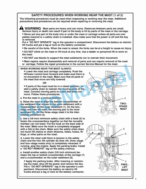
- 1.1. SAFETY PROCEDURES WHEN WORKING NEAR THE MAST
- 1.2. INTRODUCTION
- 1.3. LIFT CYLINDERS
- 1.4. CHECKS AND ADJUSTMENTS
- 2. RM0485-(07-2000)-UK-EN
- 2.1. STEERING SYSTEMS FOR ELECTRICAL LIFT TRUCKS
- 2.2. POWER STEERING MOTOR AND PUMP
- 2.3. HYDRAULIC STEERING MOTOR
- 2.4. CHECKS AND ADJUSTMENTS
- 2.5. TROUBLESHOOTING
- 3. RM0222-(04-2000)-UK-EN
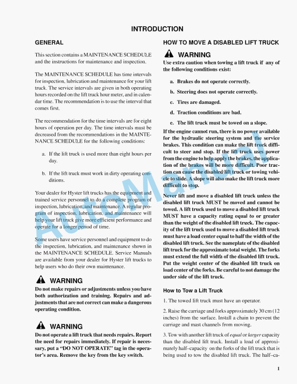
- 3.1. INTRODUCTION
- 3.2. VISTA TWO-STAGE MAST
- 3.3. VISTA FREE-LIFT MAST
- 3.4. VISTA THREE-STAGE MAST
- 3.5. VISTA FOUR-STAGE MAST
- 4. RM0001-(01-2016)-UK-EN
- 4.1. General
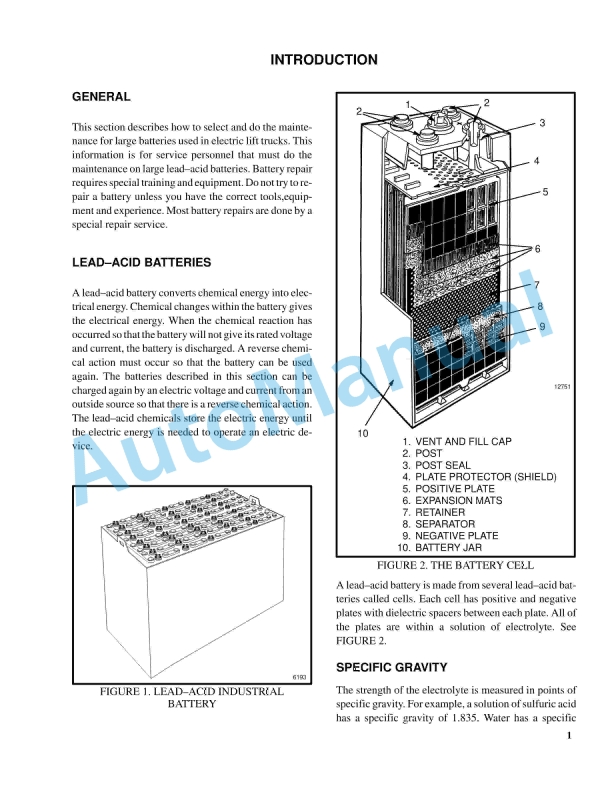
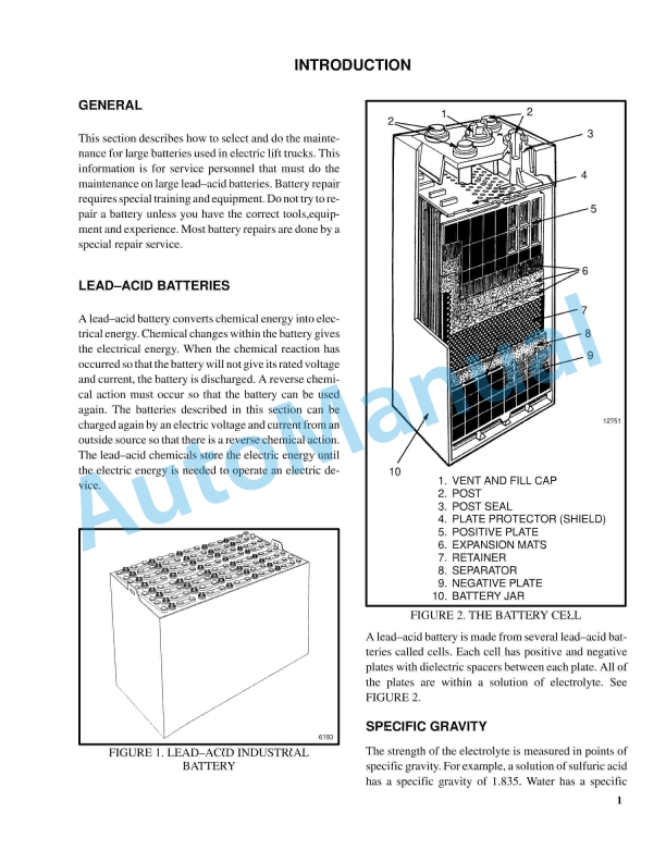
- 4.2. Lead-Acid Batteries
- 4.3. Specific Gravity
- 4.4. Chemical Reaction in a Cell
- 4.5. Electrical Terms
- 4.6. Battery Selection
- 4.7. Battery Voltage
- 4.8. Battery as a Counterweight
- 4.9. Battery Ratings
- 4.10. Battery Maintenance
- 4.11. Troubleshooting
- 5. RM0145-(02-1997)-UK-EN
- 5.1. INTRODUCTION
- 5.2. MAGNETISM
- 5.3. BASIC MOTORS
- 6. RM0103-(03-2007)-UK-EN
- 6.1. Tilt Cylinders
- 6.2. Safety Precautions Maintenance and Repair
- 6.3. General
- 6.4. Description
- 6.5. Tilt Cylinder Repair
- 6.6. Disassemble
- 6.7. Assemble
- 6.8. Tilt Cylinders With O-Ring or Single-Lip Seals
- 6.9. Tilt Cylinders for XM and XMS Models
- 6.10. Tilt Cylinders for XL, XLS, and XL 3 Models
- 6.11. Tilt Cylinders for H700-800A and Early Model H700-920B
- 6.12. Install
- 6.13. Tilt Cylinders Using Chevron Packing
- 6.14. Tilt Cylinder Leak Check
- 6.15. Tilt Cylinder Stroke and Mast Tilt Angle Adjustment
- 6.16. Torque Specifications
- 6.17. Piston Rod Nut
- 6.18. Retainer
- 6.19. Troubleshooting
- 6.20. Table 1. Movement Rates (Maximum) for Tilt Cylinders
- 7. RM0143-(02-2007)-UK-EN
- 7.1. Instrument Panel Indicators and Senders
- 7.2. Safety Precautions Maintenance and Repair
- 7.3. General
- 7.4. Description
- 7.5. Steering Column Gauges, Meters, and Indicators
- 7.6. LED Display Panel
- 7.7. Battery Discharge Indicators
- 7.8. Brush Wear Indicators
- 7.9. Motor Temperature Indicators
- 7.10. LX Series Display Panel
- 7.11. Hourmeter Functions
- 7.12. Battery Indicator Function
- 7.13. Status Code Function
- 7.14. ZX Series Display Panels
- 7.15. Display Panel
- 7.16. Basic Display Panels
- 7.17. Performance Display
- 7.18. Brush Wear Indicators
- 7.19. Adjustments – General
- 7.20. Replacement – General Information
- 7.21. Meter Replacement
- 7.22. Sender Replacement
- 7.23. Fuel Level Sender
- 7.24. Pressure and Temperature Sender
- 7.25. Seat Sensor, Operator Presence System (OPS)
- 7.26. Install
- 7.27. Operator Presence System Module Replacement
- 7.28. Install
- 7.29. ITW Display Panel Replacement
- 7.30. Column Mount Display Panel (EV-100/200ZX Motor Controllers) Repl
- 7.31. Display Panel Assembly, Replace
- 7.32. Indicator LEDs
- 7.33. Battery Indicators
- 7.34. Digital Display (Performance Display Panel Only)
- 7.35. Status Code or Performance Level Switches and Indicator LEDs (Pe
- 7.36. Basic Display Panel, Replace Parts
- 7.37. Performance Display Panel, Replace Parts
- 7.38. Dash Mount Display Panel (EV100/200ZX Motor Controllers) Replace
- 7.39. Remove and Replace
- 7.40. Specifications
- 7.41. Meter Specifications
- 7.42. Sender Specifications
- 7.43. Troubleshooting
- 7.44. Troubleshooting for Operator Presence System
- 7.45. Table 1. Troubleshooting Procedure for Operator Presence Module
- 8. RM0144-(05-1997)-UK-EN
- 8.1. ELECTRICAL WARNING DEVICES
- 9. RM0138-(06-2002)-UK-EN
- 9.1. INTRODUCTION
- 9.2. CHECKS AND ADJUSTMENTS
- 9.3. REPAIRS
- 9.4. BATTERY INDICATORS
- 9.5. CONTROLLER FOR THE BATTERY INDICATOR
- 9.6. DISPLAY PANEL COMPONENTS
- 10. RM0231-(01-2016)-UK-EN
- 10.1. General
- 11. RM0793-(03-2000)-UK-EN
- 11.1. Safety Precautions Maintenance and Repair
- 11.2. General
- 11.3. Description
- 11.4. Overhead Guard Repair
- 11.5. Install
- 11.6. Hood and Seat Assembly Repair
- 11.7. Install
- 11.8. Counterweight Repair
- 11.9. Install
- 11.10. Hydraulic Tank Repair
- 11.11. Inspect
- 11.12. Small Leaks, Repair
- 11.13. Large Leaks, Repair
- 11.14. Steam Method
- 11.15. Chemical Solution Method
- 11.16. Additional Preparations for Repair
- 11.17. Safety Labels
- 11.18. Battery Specifications
- 11.19. Table 1. Weight of Counterweights
- 12. RM0794-(05-2000)-UK-EN
- 12.1. Master Drive Unit (ZF)
- 12.2. Safety Precautions Maintenance and Repair
- 12.3. General
- 12.4. Description
- 12.5. Top Section Housing
- 12.6. Transmission Housing
- 12.7. Disassemble
- 12.8. Top Section Housing
- 12.9. Transmission Housing
- 12.10. Assemble
- 12.11. Installing Spiral Bevel Pinion Shaft
- 12.12. Measuring Bearing Movement in Bevel Pinion Shaft
- 12.13. Assembly of Helical Gear
- 12.14. Assembling Crown Gear and Wheel Shaft
- 12.15. Assembling Transmission Housing Cover
- 12.16. Assembling Input Motor Pinion Gear
- 12.17. Inspecting Top Section Housing
- 12.18. Measuring Pivoting Bearing Movement
- 12.19. Installing Top Section Housing
- 12.20. Install
- 12.21. Tooth Contact Pattern Adjustment
- 12.22. Changing Transmission Oil
- 12.23. Troubleshooting
- 12.24. Table 1. Tooth Contact Pattern
- 13. RM0795-(04-2000)-UK-EN
- 13.1. Master Drive Unit (Kordel)
- 13.2. Safety Precautions Maintenance and Repair
- 13.3. General
- 13.4. Description
- 13.5. Upper Section
- 13.6. Lower Section
- 13.7. Drive Unit Repair
- 13.8. Disassemble
- 13.9. Assemble
- 13.10. General
- 13.11. Assemble Component Subassemblies
- 13.12. Assemble Components Into Lower Section
- 13.13. Assemble Upper and Lower Sections
- 13.14. Install
- 13.15. Check and Change Transmission Oil
- 13.16. Tooth Contact Pattern Adjustment
- 13.17. Troubleshooting
- 13.18. Table 1. Tooth Contact Pattern
- 14. RM0797-(03-2000)-UK-EN
- 14.1. Steering Control Unit
- 14.2. Safety Precautions Maintenance and Repair
- 14.3. General
- 14.4. Description
- 14.5. Operation
- 14.6. Steering Wheel and Column Assembly Repair
- 14.7. Steering Column Assembly Repair
- 14.8. Remove and Disassemble
- 14.9. Assemble and Install
- 14.10. Steering Control Unit, Disassemble
- 14.11. Steering Control Unit, Clean
- 14.12. Steering Control Unit, Assemble
- 14.13. System Air Removal
- 14.14. Troubleshooting
- 15. RM0796-(03-2000)-UK-EN
- 15.1. Steering System
- 15.2. Safety Precautions Maintenance and Repair
- 15.3. General
- 15.4. Description
- 15.5. Steering Wheel and Column Assembly
- 15.6. Steering Control Unit Repair
- 15.7. Install
- 15.8. Hydraulic Steering Motor Repair
- 15.9. Description
- 15.10. Disassemble
- 15.11. Clean and Inspect
- 15.12. Assemble
- 15.13. Install
- 15.14. Direction Control Lever Repair
- 15.15. Assemble
- 15.16. Install
- 15.17. Power Steering Adjustments
- 15.18. Air in Steering System
- 15.19. Steering Pressure
- 15.20. Steering Chain, Adjust
- 15.21. Troubleshooting
- 16. RM0803-(03-2000)-UK-EN
- 16.1. Brake System
- 16.2. Safety Precautions Maintenance and Repair
- 16.3. General
- 16.4. Description and Operation
- 16.5. Master Cylinder Repair
- 16.6. Remove and Disassemble
- 16.7. Clean and Inspect
- 16.8. Assemble and Install
- 16.9. Service and Parking Brakes Repair
- 16.10. Remove and Disassemble
- 16.11. Inspect
- 16.12. Assemble and Install
- 16.13. Brake System Air Removal
- 16.14. Service Brakes Adjustment
- 16.15. Brake Pedal Adjustment
- 16.16. Parking Brake Adjustment
- 16.17. Troubleshooting
- 17. RM0802-(02-2009)-UK-EN
- 17.1. Hydraulic System
- 17.2. Safety Precautions Maintenance and Repair
- 17.3. General
- 17.4. Description
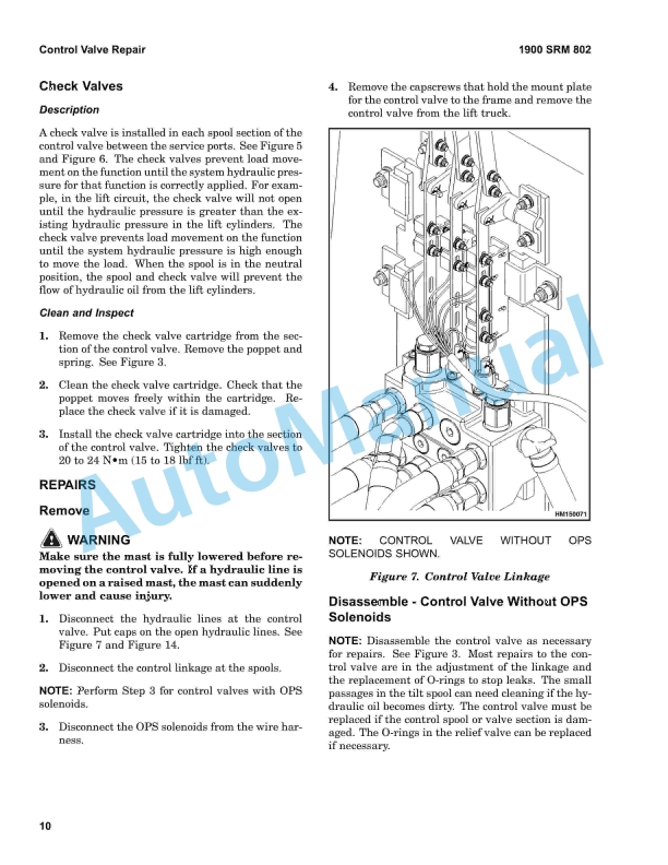
- 17.5. Control Valve Repair
- 17.6. Description
- 17.7. Operation
- 17.8. Tilt and Auxiliary
- 17.9. Relief Valve
- 17.10. Check Valves
- 17.11. Repairs
- 17.12. Disassemble – Control Valve Without OPS Solenoids
- 17.13. Disassemble – Control Valve With OPS Solenoids
- 17.14. Relief Valve Repair – Control Valve Without OPS Solenoids
- 17.15. Relief Valve Repair – Control Valve With OPS Solenoids
- 17.16. Clean and Inspect
- 17.17. Assemble – Control Valve Without OPS Solenoids
- 17.18. Assemble – Control Valve With OPS Solenoids
- 17.19. Install
- 17.20. Relief Valve Check
- 17.21. Relief Valve
- 17.22. Control Levers, Linkage, and Switches
- 17.23. Hydraulic Pump Repair
- 17.24. Description
- 17.25. Repairs
- 17.26. Seal, Replace
- 17.27. Install
- 17.28. Specifications
- 17.29. Relief Valves Pressures
- 17.30. Hydraulic System Capacity
- 17.31. Troubleshooting
- 17.32. Hydraulic Pump
- 17.33. Control Valve
- 18. RM0806-(10-2001)-UK-EN
- 18.1. Sevcon SC2126 Motor Controller
- 18.2. Safety Precautions Maintenance and Repair
- 18.3. General
- 18.4. Lift Truck Control
- 18.5. Plugging
- 18.6. Contactors
- 18.7. Circuit Protection
- 18.8. Current Limit
- 18.9. Controller Operation
- 18.10. General Operation
- 18.11. Operating Frequency
- 18.12. Temperature Monitoring
- 18.13. Safe Operating Area (SOA)
- 18.14. Undervoltage and Overvoltage Protection
- 18.15. Diagnostic LED
- 18.16. Fault Clearance
- 18.17. Software Version and Revision Indication
- 18.18. Setup Menu
- 18.19. Multi Languages
- 18.20. Power Circuit Descriptions
- 18.21. Traction Operation
- 18.22. Start Up Sequence
- 18.23. Static Return to Off (SRO)
- 18.24. Seat Switch
- 18.25. Acceleration Delay
- 18.26. Deceleration Delay
- 18.27. Regenerative Braking
- 18.28. Plug Braking
- 18.29. Brake Constant Factor
- 18.30. Antirollback
- 18.31. Analog Inputs
- 18.32. Traction Accelerator
- 18.33. Digital Switch Inputs
- 18.34. Contactors
- 18.35. Contactor Chopping
- 18.36. Fail-Safe
- 18.37. Pump Operation
- 18.38. Pump Speeds and Priorities
- 18.39. Additive Speeds
- 18.40. Power Steer Speed
- 18.41. Pump Inhibit Input
- 18.42. Pump Speed Compensation
- 18.43. Calibration and Adjustments
- 18.44. Traction Personalities (Controller Adjustments)
- 18.45. Traction Status Information
- 18.46. Traction Test Information
- 18.47. BDI Adjustments
- 18.48. Fault Log
- 18.49. Setup Menu (Enables/Disables Features)
- 18.50. Pump Personalities (Controller Adjustments)
- 18.51. Pump Status Information
- 18.52. Pump Test Information
- 18.53. Pump Setup Menu
- 18.54. Traction and Pump Adjustment Descriptions
- 18.55. Setup Menu Descriptions
- 18.56. Controller Connections
- 18.57. Power Connections
- 18.58. Controller Connections
- 18.59. Contactor Connections
- 18.60. Contactor Types
- 18.61. Fuse Ratings
- 18.62. Back Panel Connectors
- 18.63. Connector A – 24 Pin
- 18.64. Connector B – 12 Pin
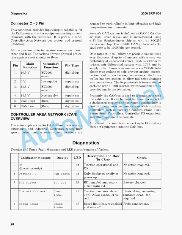
- 18.65. Connector C – 6 Pin
- 18.66. Controller Area Network (CAN) Overview
- 18.67. Diagnostics
- 18.68. Service and Fault Logs
- 18.69. Service Log
- 18.70. Fault Log
- 18.71. Technical Specifications
- 18.72. Environmental
- 18.73. Mechanical
- 18.74. Electrical
- 18.75. Voltage Specifications
- 18.76. Current Specifications
- 18.77. Miscellaneous Controller Specifications
- 18.78. Contactor Repair
- 18.79. General
- 18.80. Remove Contactor Assembly
- 18.81. Contactor Contacts
- 18.82. Control Switches
- 18.83. Key Switch
- 18.84. Seat Switch
- 18.85. Start Switch
- 18.86. Brake Pedal Adjustment
- 18.87. Accelerator Pedal Adjustment
- 18.88. Table 1. Over- and Undervoltage Protection
- 19. RM0798-(03-2010)-UK-EN
- 19.1. Periodic Maintenance
- 19.2. Safety Precautions Maintenance and Repair
- 19.3. General
- 19.4. How to Move Disabled Lift Truck
- 19.5. How to Tow Lift Truck
- 19.6. How to Put Lift Truck on Blocks
- 19.7. How to Raise Load Wheels
- 19.8. How to Raise Steer Wheels
- 19.9. How to Clean a Lift Truck
- 19.10. Safety Procedures When Working Near Mast
- 19.11. Maintenance Schedule
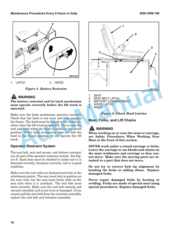
- 19.12. Maintenance Procedures Every 8 Hours or Daily
- 19.13. Checks Before Operation
- 19.14. Hydraulic System
- 19.15. Battery
- 19.16. Battery Restraint System
- 19.17. Operator Restraint System
- 19.18. Mast, Forks, and Lift Chains
- 19.19. Lift Chain Adjustments
- 19.20. Tires and Wheels
- 19.21. Check Operation
- 19.22. Gauges and Horn
- 19.23. Control Levers and Pedals
- 19.24. Lift System Operation
- 19.25. Service Brakes
- 19.26. Parking Brake
- 19.27. Steering System
- 19.28. Maintenance Procedures Every 500 Hours or 3 Months
- 19.29. Hydraulic Tank Breather
- 19.30. Wheel Nut Torques
- 19.31. Master Drive Unit (MDU)
- 19.32. Lift Chains
- 19.33. Safety Labels
- 19.34. Brake Fluid
- 19.35. Other Lubrication
- 19.36. Electrical Inspection
- 19.37. Contactors
- 19.38. Motor Brushes
- 19.39. Maintenance Procedures Every 2000 Hours or Yearly


%20Service%20Manual&url=https://pdfrepairmanual.com/docs/hyster-c203-a1-00-1-50xl-service-manual/&media=https://pdfrepairmanual.com/wp-content/uploads/2026/01/hyster-c203-a100-150xl-service-manual-1.jpg)

%20Service%20Manual&url=https://pdfrepairmanual.com/docs/hyster-c098-e3-50-5-50xl-service-manual/&media=https://pdfrepairmanual.com/wp-content/uploads/2026/01/hyster-c098-e350-550xl-service-manual-1.jpg)

%20Service%20Manual&url=https://pdfrepairmanual.com/docs/hyster-c005-h60-90c-service-manual/&media=https://pdfrepairmanual.com/wp-content/uploads/2026/01/hyster-c005-h60-90c-service-manual-1.jpg)


%20Maintenance%20Schedule&url=https://pdfrepairmanual.com/docs/hyster-c098-e3-50-5-50xl-e4-50xls-maintenance-schedule/&media=https://pdfrepairmanual.com/wp-content/uploads/2026/01/hyster-c098-e350-550xl-e450xls-maintenance-schedule-1.jpg)
%20Service%20Manual&url=https://pdfrepairmanual.com/docs/hyster-b160-j25-35bs-service-manual/&media=https://pdfrepairmanual.com/wp-content/uploads/2026/01/hyster-b160-j25-35bs-service-manual-1.jpg)
There are no reviews yet.