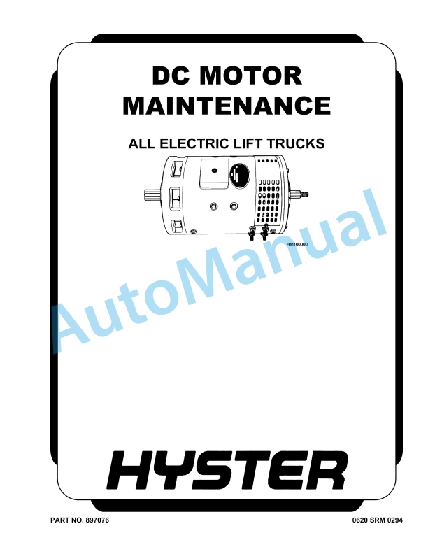
Hyster DC Motor All Electric Lift Truck Maintenance And Repair
$30.00
- Type Of Manual: Maintenance And Repair
- Number of Pages: 1520
- Size: 61.9MB
- Format: PDF
Description
-
Model List:
- DC Motor All Electric Lift Truck
- 1. RM0294-(03-2008)-US-EN
- 1.1. General
- 1.2. Brush and Commutator Inspection
- 1.3. Brush Replacement
- 1.4. Stoning the Commutator
- 1.5. Motors Repair
- 1.6. Brush Alignment, Traction and Hydraulic Motors
- 1.7. Tests for Damaged Field and Armature
- 1.8. Troubleshooting
- 2. RM0316-(08-2006)-US-EN
- 2.1. Steering Axle
- 2.2. Safety Precautions Maintenance and Repair
- 2.3. General
- 2.4. Description
- 2.5. Steering Axle Assembly Repair
- 2.6. Install
- 2.7. Wheels and Hubs Repair
- 2.8. Remove and Disassemble
- 2.9. Assemble and Install
- 2.10. Spindles, Bearings, and Tie Rods Repair
- 2.11. Install
- 2.12. Steering Cylinder Repair
- 2.13. Remove and Disassemble
- 2.14. Clean and Inspect
- 2.15. Assemble and Install
- 2.16. Torque Specifications
- 2.17. Troubleshooting
- 3. RM0485-(08-2003)-US-EN
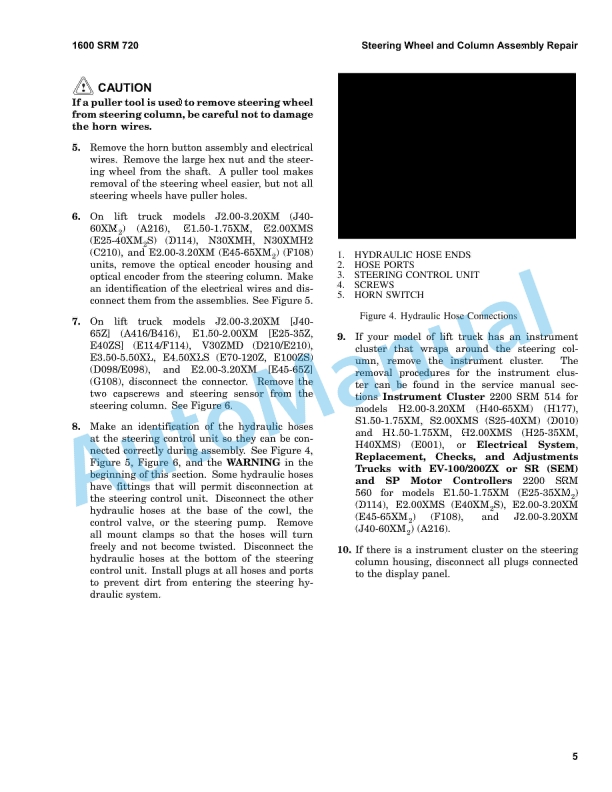
- 3.1. Steering System for Electric Lift Trucks
- 3.2. Safety Precautions Maintenance and Repair
- 3.3. General
- 3.4. Description
- 3.5. Steering Wheel and Column Assembly Repair
- 3.6. Assembly Components, Remove
- 3.7. Assembly Components, Install
- 3.8. Power Steering Motor and Pump
- 3.9. Description
- 3.10. Remove and Disassemble, Models E1.25-3.00XL (E25-60XL), J2.00-3.
- 3.11. Remove and Disassemble, Models E3.50-5.50XL (E70-120XL, E70-120X
- 3.12. Remove and Disassemble, Models J2.00-3.20XM (J40-60XM, J40-60XM
- 3.13. Remove and Disassemble, Models A1.00-1.50XL (A20-30XL)
- 3.14. Remove and Disassemble, Models E1.50-2.00XMS (E25-40XMS, E25-40X
- 3.15. Assemble and Install – All models with a vertical mount except J
- 3.16. Assemble and Install, Models J2.00-3.20XM (J40-60XM, J40-60XM 2
- 3.17. Assemble and Install, Models E1.50-2.00XMS (E25-40XMS, E25-40XM
- 3.18. Power Steering Pump, Repair
- 3.19. Seal, Replace
- 3.20. Hydraulic Steering Motor
- 3.21. Description
- 3.22. Hydraulic Steering Motor Repairs
- 3.23. Disassemble
- 3.24. Clean and Inspect
- 3.25. Assemble
- 3.26. Install
- 3.27. Steering System Air Removal
- 3.28. Steering Pressure Check
- 3.29. Steering Chain Tension Check (Unit With MDU Only)
- 3.30. Optical Encoder and Activator Circuits Check
- 3.31. Troubleshooting
- 4. RM0512-(08-2003)-US-EN
- 4.1. Steering Housing and Control Unit
- 4.2. Safety Precautions Maintenance and Repair
- 4.3. General
- 4.4. Description
- 4.5. Operation
- 4.6. Steering Wheel and Column Assembly Repair
- 4.7. Steering Column Assembly, Remove
- 4.8. Steering Control Unit
- 4.9. Steering Column Assembly, Install
- 4.10. System Air Removal
- 4.11. Troubleshooting
- 5. RM0514-(01-2004)-US-EN
- 5.1. Instrument Cluster
- 5.2. Safety Precautions Maintenance and Repair
- 5.3. General
- 5.4. Description
- 5.5. Display Panels on Steering Column, Internal Combustion
- 5.6. Display Panels on Steering Column, Electric Lift Trucks
- 5.7. Standard Display Panel
- 5.8. Enhanced Display Panel
- 5.9. Curtis 1215 Display Panel
- 5.10. Description and Features
- 5.11. Operation
- 5.12. Cluster-Type Display Panel (Internal Combustion) Replacement
- 5.13. Remove and Disassemble
- 5.14. Assemble and Install
- 5.15. Cluster Display Panel (Electric Lift Truck) Replacement
- 5.16. Display Panel Assembly, Replace
- 5.17. LED Indicators
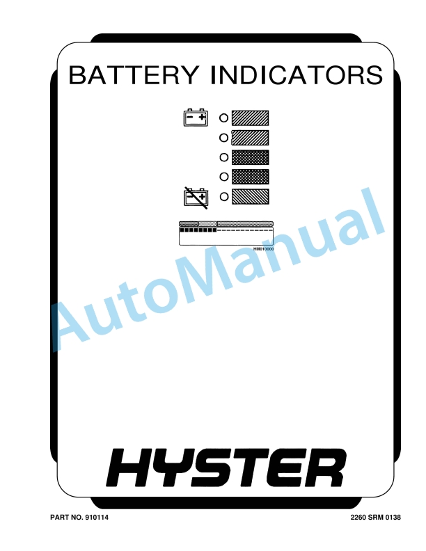
- 5.18. Battery Indicators
- 5.19. Digital Display (Enhanced Display Panel Only)
- 5.20. Status Code or Performance Level Switches and LED indicators (En
- 5.21. Standard Display Panel Parts, Replace
- 5.22. Enhanced Display Panel Parts, Replace
- 5.23. Curtis 1215 Display Panel Replacement
- 5.24. Install
- 5.25. Table 1. Instrument Cluster, Internal Combustion
- 6. RM0521-(03-2006)-US-EN
- 6.1. Safety Precautions Maintenance and Repair
- 6.2. General
- 6.3. Description and Operation
- 6.4. Carriages
- 6.5. Mast Mounts
- 6.6. Two-Stage Mast, Limited Free-Lift (LFL)
- 6.7. Description and Operation
- 6.8. Two-Stage Mast, Full Free-Lift (FFL)
- 6.9. Description and Operation
- 6.10. Three-Stage Mast, Full Free-Lift (FFL)
- 6.11. Description and Operation
- 6.12. Four-Stage Mast
- 6.13. Description and Operation
- 6.14. Cylinder Cushion During Lifting Sequence
- 6.15. Cylinder Cushion During Lowering Sequence
- 7. RM0522-(07-2010)-US-EN
- 7.1. Mast Repairs
- 7.2. Safety Precautions Maintenance and Repair
- 7.3. General
- 7.4. Safety Procedures When Working Near Mast
- 7.5. Fork Repair
- 7.6. Install
- 7.7. Carriages Repair
- 7.8. Standard Carriage, Remove
- 7.9. Hang-On Sideshift Carriage, Remove
- 7.10. Standard Carriage and Hang-On Sideshift Carriage, Repair
- 7.11. Standard Carriage, Install
- 7.12. Hang-On Sideshift Carriage, Install
- 7.13. Integral Sideshift Carriage
- 7.14. Clean and Inspect
- 7.15. Install
- 7.16. Mast Repair
- 7.17. Two-Stage LFL and Two-Stage FFL Masts, Disassemble
- 7.18. Three-Stage FFL Mast
- 7.19. Disassemble
- 7.20. Mast and Chains, Clean and Inspect
- 7.21. Two-Stage LFL and Two-Stage FFL Mast, Assemble
- 7.22. Three-Stage FFL Mast, Assemble
- 7.23. Install
- 7.24. Lift Cylinders Repair
- 7.25. Main Lift Cylinders, Remove
- 7.26. Free-Lift Cylinder, Remove
- 7.27. Cylinders, Disassemble
- 7.28. Two-Stage Full Free-Lift Mast, Right-Hand Main Lift Cylinder
- 7.29. Two-Stage Full Free-Lift Mast, Left-Hand Main Lift Cylinder
- 7.30. Two-Stage Limited Free-Lift Mast and Three-Stage Full Free-Lift
- 7.31. Two-Stage Limited Free-Lift Mast and Three-Stage Full Free-Lift
- 7.32. Two-Stage Full Free-Lift Mast and Three-Stage Full Free-Lift Mas
- 7.33. Clean and Inspect
- 7.34. Cylinders, Assemble
- 7.35. Two-Stage Full Free-Lift Mast, Right-Hand Main Lift Cylinder
- 7.36. Two-Stage Full Free-Lift Mast, Left-Hand Main Lift Cylinder
- 7.37. Two-Stage Limited Free-Lift Mast and Three-Stage Full Free-Lift
- 7.38. Two-Stage Limited Free-Lift Mast and Three-Stage Full Free-Lift
- 7.39. Two-Stage Full Free-Lift Mast and Three-Stage Full Free-Lift Mas
- 7.40. Main Lift Cylinders, Install
- 7.41. Free-Lift Cylinder, Install
- 7.42. Header Hose Arrangements
- 7.43. Two-Stage LFL Mast, New Hose Install
- 7.44. Two-Stage LFL Mast, Adjust Hoses After Installation
- 7.45. Two-Stage FFL Mast, New Hose Install
- 7.46. Two-Stage FFL Mast, Adjust Hoses After Installation
- 7.47. Three-Stage FFL Mast, New Hose Install
- 7.48. Three-Stage FFL Mast, Adjust Hoses After Installation
- 7.49. Header Hose Arrangement
- 7.50. Two-Stage LFL Mast, New Hose Install
- 7.51. Two-Stage LFL Mast, Adjust Hoses After Installation
- 7.52. Two-Stage FFL Mast, New Hose Install
- 7.53. Two-Stage FFL Mast, Adjust Hoses After Installation
- 7.54. Three-Stage FFL Mast, New Hose Install
- 7.55. Three-Stage FFL Mast, Adjust Hoses After Install
- 7.56. Lift and Tilt System Leak Check
- 7.57. Lift Cylinders Leak Check
- 7.58. Tilt Cylinders Leak Check
- 7.59. Tilt Cylinders Adjustment
- 7.60. Lift Chains Adjustment
- 7.61. Mast Adjustment
- 7.62. Carriage Adjustment
- 7.63. Troubleshooting
- 7.64. Table 1. Hook-Type Carriage Chain Adjustment
- 7.65. Table 2. Pin-Type Carriage Chain Adjustment
- 8. RM0552-(01-2004)-US-EN
- 8.1. Periodic Maintenance
- 8.2. Safety Precautions Maintenance and Repair
- 8.3. General
- 8.4. Serial Number Data
- 8.5. How to Move Disabled Lift Truck
- 8.6. How to Tow Lift Truck
- 8.7. How to Put Lift Truck on Blocks
- 8.8. How to Raise Drive Tires
- 8.9. How to Raise Steering Tires
- 8.10. Maintenance Schedule
- 8.11. Maintenance Procedures Every 8 Hours or Daily
- 8.12. How to Make Checks With Key OFF
- 8.13. Tires and Wheels
- 8.14. Forks, Mast, and Lift Chains, Inspect
- 8.15. Safety Labels
- 8.16. Steering Column Latch
- 8.17. Operator Restraint System
- 8.18. Battery Restraint System E1.50-3.20XM, E2.00XMS (E25-65XM, E25-6
- 8.19. Battery Restraint System J2.00-3.20XM (J40-60XM and J40-60XM 2 )
- 8.20. Battery
- 8.21. Hydraulic System
- 8.22. How to Make Checks With Key ON
- 8.23. Gauges, Horn, and Fuses
- 8.24. Steering System
- 8.25. Service Brakes
- 8.26. Parking Brake
- 8.27. Control Levers and Pedals
- 8.28. Direction and Speed Control Pedals
- 8.29. Lift System Operation
- 8.30. Maintenance Procedures Every 250 Hours or 6 Weeks
- 8.31. Steering Tie Rods
- 8.32. Steering King Pins, Trucks Only
- 8.33. Maintenance Procedures Every 500 Hours or 3 Months
- 8.34. Hydraulic Tank Breather
- 8.35. Differential and Speed Reducer
- 8.36. Wheel Nut Torques
- 8.37. Steering Axle Spindles
- 8.38. Steering Tie Rods
- 8.39. Lift Chains
- 8.40. Wear Check
- 8.41. Brake Fluid
- 8.42. Other Lubrication
- 8.43. Seat Brake, Models E1.50-3.20XM, E2.00XMS (E25-65XM and E25-65XM
- 8.44. Electrical Inspection
- 8.45. Contactors
- 8.46. Motor Brushes
- 8.47. Motor Brushes, General
- 8.48. Maintenance Procedures Every 1000 Hours or 6 Months
- 8.49. Lift Chains
- 8.50. Check Upper and Lower Bearings, Integral Sideshift Carriage
- 8.51. Maintenance Procedures Every 2000 Hours or Yearly
- 8.52. Hydraulic System
- 8.53. Change Filter for Hydraulic Oil
- 8.54. Change Hydraulic Oil
- 8.55. Differential and Speed Reducer
- 8.56. Service Brakes
- 8.57. Contactors
- 8.58. Wheel Bearings
- 8.59. Steer Wheels, Lubrication
- 8.60. Drive Wheels, Lubrication
- 8.61. Lift Chains
- 8.62. Replace Upper and Lower Bearings, Integral Sideshift Carriage
- 8.63. Steering Axle
- 8.64. King Pins and Rod Ends (Steering Cylinders)
- 8.65. Other Lubrication
- 8.66. Battery Maintenance
- 8.67. How to Charge Battery
- 8.68. How to Change Battery
- 8.69. General
- 8.70. Change Battery, E1.50-3.20XM, E2.00XMS (E25-65XM and E25-65XM 2
- 8.71. Change J2.00-3.20XM (J40-60XM and J40-60XM 2 ) Battery
- 8.72. Lift and Tilt System Leak Check
- 8.73. Lift Cylinders Leak Check
- 8.74. Tilt Cylinders Leak Check
- 8.75. Safety Procedures When Working Near Mast
- 8.76. Lift Chain Adjustments
- 8.77. PMT Circuit Check
- 8.78. Welding Repairs
- 8.79. Overhead Guard Changes
- 8.80. Wheels and Tire Maintenance
- 8.81. Tires and Wheels, E1.50-3.20XM, E2.00XMS (E25-65XM and E25-65XM
- 8.82. Remove Wheels From Lift Truck
- 8.83. Remove and Install Tire on Wheel
- 8.84. Pneumatic Tires and Wheels J2.00-3.20XM (J40-60XM and J40-60XM 2
- 8.85. Remove Wheels From Lift Truck
- 8.86. Remove Wheel From Pneumatic Tire
- 8.87. Install Wheel in Pneumatic Tire
- 8.88. Install Three- or Four-Piece Wheel in Pneumatic Tire
- 8.89. Add Air to Tires
- 8.90. Wheels, Install
- 8.91. Solid Rubber Tires on Pneumatic Wheels
- 8.92. Remove Wheels From Lift Truck
- 8.93. Remove Solid Rubber Tire From Pneumatic Wheel
- 8.94. Install Solid Rubber Tire on Pneumatic Wheel
- 8.95. Wheels, Install
- 8.96. Solid Rubber Tire, Change
- 8.97. Remove and Install Tire on Wheel
- 8.98. Remove Wheel From Tire
- 8.99. Install Wheel in Tire
- 8.100. SIT Tire, Change
- 8.101. Remove SIT Solid Tire From Wheel
- 8.102. Install SIT Solid Tire on Wheel
- 8.103. Adhesives and Sealants
- 8.104. Table 1. Maintenance Schedule
- 9. RM0551-(08-2003)-US-EN
- 9.1. Electrical Diagrams
- 9.2. Safety Precautions Maintenance and Repair
- 10. RM0557-(08-2003)-US-EN
- 10.1. EV-100ZX SCR Motor Controller
- 10.2. Safety Precautions Maintenance and Repair
- 10.3. General
- 10.4. Model Number Data For EV-100ZX Controller
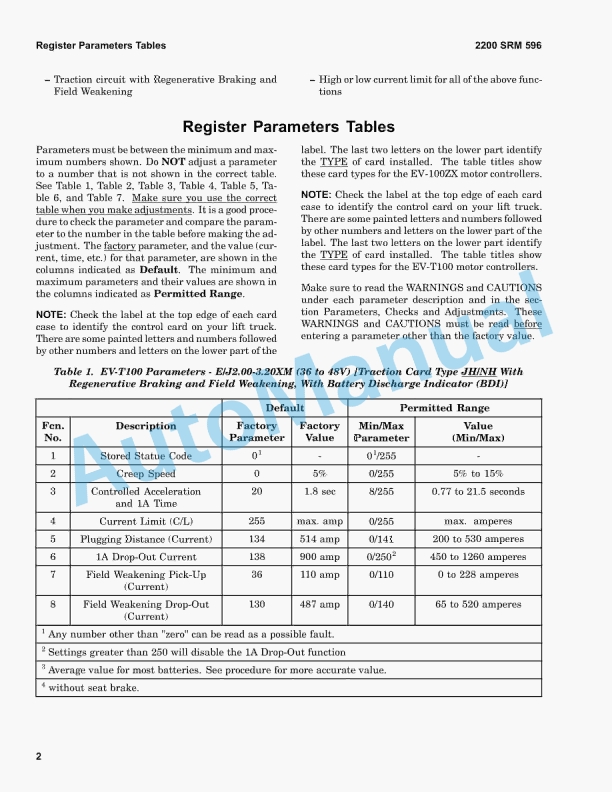
- 10.5. Register Parameters
- 10.6. General
- 10.7. Function Numbers
- 10.8. Control Card, Checks and Adjustments
- 10.9. Handset
- 10.10. How to Check and Adjust Registers
- 10.11. How to Scroll through Fault Codes and Clear Them
- 10.12. Checks and Adjustments on Workbench
- 10.13. When Handset Is Connected to Control Card Installed In Lift Truc
- 10.14. Function Numbers 1 through 15
- 10.15. Function Numbers 16 through 30
- 10.16. Function Numbers 48 through 62
- 10.17. Control Cards
- 10.18. Function Number Descriptions
- 10.19. Traction Control Cards (Label Letters – ZH and ZY)
- 10.20. Function Number 1 STORED STATUS CODE
- 10.21. Function Number 2 CREEP SPEED
- 10.22. Function Number 3 CONTROLLED ACCELERATION AND 1A TIME
- 10.23. Function Number 4 CURRENT LIMIT
- 10.24. Function Number 5 PLUGGING DISTANCE (CURRENT)
- 10.25. Function Number 6 1A DROP OUT CURRENT
- 10.26. Function Number 7 FIELD WEAKENING PICK UP
- 10.27. Function Number 8 FIELD WEAKENING DROP OUT
- 10.28. Function Number 9 REGENERATIVE BRAKING CURRENT LIMIT
- 10.29. Function Number 10 REGENERATIVE BRAKING START
- 10.30. Function Number 13 SPEED LIMIT 3 (SL3)
- 10.31. Function Number 14 INTERNAL RESISTANCE COMPENSATION
- 10.32. Function Number 15 BATTERY VOLTS
- 10.33. Function Numbers GREATER THAN 15
- 10.34. Function Number 16 PEDAL POSITION PLUG
- 10.35. Function Number 17 CARD TYPE SELECTION
- 10.36. Function Number 18 STEERING PUMP TIME DELAY
- 10.37. Function Number 19 MAINTENANCE ALERT (Tens/Units)
- 10.38. Function Number 20 MAINTENANCE ALERT (Thousands/Hundreds)
- 10.39. Function Number 21 MAINTENANCE SPEED LIMIT
- 10.40. Function Numbers 22 Through 28 TEMPORARY DATA REGISTERS
- 10.41. Function Number 29 HOURMETER (Tens/Units)


%20Service%20Manual&url=https://pdfrepairmanual.com/docs/hyster-c001-h25-35xl-service-manual/&media=https://pdfrepairmanual.com/wp-content/uploads/2026/01/hyster-c001-h25-35xl-service-manual-1.jpg)


%20Service%20Manual&url=https://pdfrepairmanual.com/docs/hyster-b168-j2-00-3-00xl-service-manual/&media=https://pdfrepairmanual.com/wp-content/uploads/2026/01/hyster-b168-j200-300xl-service-manual-1.jpg)
%20Service%20Manual&url=https://pdfrepairmanual.com/docs/hyster-c010-s1-50-2-00xms-service-manual/&media=https://pdfrepairmanual.com/wp-content/uploads/2026/01/hyster-c010-s150-200xms-service-manual-1.jpg)
%20Service%20Manual&url=https://pdfrepairmanual.com/docs/hyster-b210-n30ah-service-manual/&media=https://pdfrepairmanual.com/wp-content/uploads/2026/01/hyster-b210-n30ah-service-manual-1.jpg)

%20Service%20Manual&url=https://pdfrepairmanual.com/docs/hyster-c098-e3-50-5-50xl-service-manual/&media=https://pdfrepairmanual.com/wp-content/uploads/2026/01/hyster-c098-e350-550xl-service-manual-1.jpg)

There are no reviews yet.