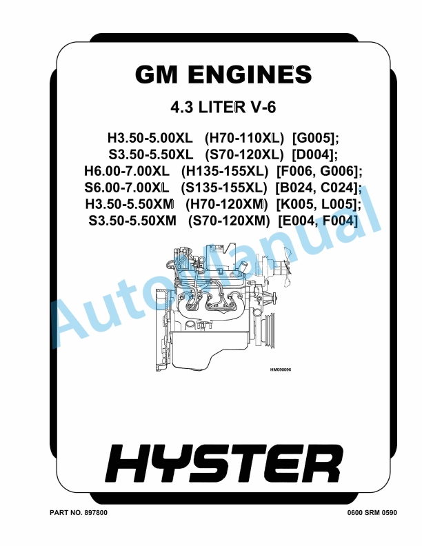
Hyster 4.3 Liter V-6 GM Engines Maintenance And Repair
$30.00
- Type Of Manual: Maintenance And Repair
- Number of Pages: 1728
- Size: 35.7MB
- Format: PDF
Description
- 1. RM0590-(04-2014)-UK-EN
- 2. RM0002-(01-2016)-UK-EN
- 2.1. General
- 2.2. Description
- 2.3. Alternator Repair
- 2.4. General Check and Adjustment
- 2.5. Low Output Check (Type A or Type B)
- 2.6. High Output Check (Type A or Type B)
- 2.7. Brushes Circuit Check
- 2.8. Diodes Check
- 2.9. Diode Bridge Check
- 2.10. Rotor Field Winding Check
- 2.11. Stator Windings Check
- 2.12. Voltage Regulator Check
- 2.13. Troubleshooting
- 3. RM0231-(01-2016)-UK-EN
- 3.1. General
- 4. RM0736-(07-2010)-UK-EN
- 4.1. Safety Precautions Maintenance and Repair
- 4.2. General
- 4.3. Description and Operation
- 4.4. Carriages
- 4.5. Two-Stage Mast With Limited Free-Lift
- 4.6. Two-Stage Mast With Full Free-Lift
- 4.7. Three-Stage Mast With Full Free-Lift
- 4.8. Safety Procedures When Working Near Mast
- 4.9. Fork Replacement
- 4.10. Install
- 4.11. Carriage Repair
- 4.12. Sideshift Carriage Repair
- 4.13. Disassemble
- 4.14. Assemble
- 4.15. Install
- 4.16. Two-Stage Mast With Limited Free-Lift Repair
- 4.17. Remove, H3.50-5.50XM (H70-120XM) Model Lift Trucks
- 4.18. Remove, S3.50-5.50XM (S70-120XM), E3.50-5.50XL 3 (E70-120XL 3 )
- 4.19. Disassemble
- 4.20. Clean and Inspect
- 4.21. Assemble
- 4.22. Install, H3.50-5.50XM (H70-120XM) Lift Truck Models
- 4.23. Install, S3.50-5.50XM (S70-120XM), E3.50-5.50XL 3 (E70-120XL 3 )
- 4.24. Two-Stage Mast With Full Free-Lift Repair
- 4.25. Disassemble
- 4.26. Clean and Inspect
- 4.27. Assemble
- 4.28. Install
- 4.29. Three-Stage Mast With Full Free-Lift Repair
- 4.30. Disassemble
- 4.31. Clean and Inspect
- 4.32. Assemble
- 4.33. Install
- 4.34. Mast Operation Check
- 4.35. Lift and Tilt System Leak Check
- 4.36. Lift System
- 4.37. Tilt System
- 4.38. Tilt Cylinder Stroke and Backward Tilt Angle Adjustment
- 4.39. Lift Chain Adjustments
- 4.40. Mast Adjustments
- 4.41. Carriage Adjustment
- 4.42. Troubleshooting
- 4.43. Table 1. Tilt Cylinder Leak Check Specifications, S3.50-5.50XM (
- 4.44. Table 2. Hook-Type Carriage Chain Adjustment
- 4.45. Table 3. Pin-Type Carriage Chain Adjustment
- 5. RM0741-(03-2005)-UK-EN
- 5.1. Lift Cylinders
- 5.2. Safety Precautions Maintenance and Repair
- 5.3. Safety Procedures When Working Near Mast
- 5.4. General
- 5.5. Description
- 5.6. Lowering Control Valve (Velocity Fuse)
- 5.7. Lift Cylinder Repair
- 5.8. Disassemble
- 5.9. Assemble
- 5.10. Install
- 5.11. Lift System Leak Check
- 5.12. Troubleshooting
- 6. RM0744-(09-2003)-UK-EN
- 6.1. Carbureted Engine Management System (CEMS)
- 6.2. Safety Precautions Maintenance and Repair
- 6.3. Description
- 6.4. Ignition Control System
- 6.5. Setting Timing Reference
- 6.6. Idle Speed Control System
- 6.7. Curb Idle Setting Procedure
- 6.8. Governor Control System
- 6.9. Closed-Loop Fuel System
- 6.10. Closed-Loop Fuel Control
- 6.11. Entering Closed-Loop Control
- 6.12. Normal Closed-Loop Operation
- 6.13. Closed-Loop Diagnostics
- 6.14. Tune Valve Action at Engine Shutdown
- 6.15. Diagnostic System
- 6.16. Closed-Loop Diagnostic Troubleshooting
- 6.17. Diagnostic Troubleshooting
- 6.18. Table 1. Diagnostic Codes
- 6.19. Table 2. Diagnostic Troubleshooting
- 7. RM0755-(11-2001)-UK-EN
- 7.1. Starter
- 7.2. Safety Precautions Maintenance and Repair
- 7.3. General
- 7.4. Description
- 7.5. Yoke Assembly
- 7.6. Armature Assembly
- 7.7. Clutch Assembly
- 7.8. Magnetic Switch Assembly
- 7.9. Operation
- 7.10. Starter Repair
- 7.11. Disassemble
- 7.12. Assemble
- 7.13. Install
- 7.14. General Checks and Adjustments
- 7.15. Armature Tests
- 7.16. Armature Short Circuit Test
- 7.17. Armature Winding Ground Test
- 7.18. Commutator Run-Out Test
- 7.19. Yoke Test
- 7.20. Brush and Brush Holder Check
- 7.21. Brush Holder Insulation Test
- 7.22. Clutch Test
- 7.23. Magnetic Switch Test
- 7.24. Pull-In Test
- 7.25. Hold-In Test
- 7.26. Return Test
- 7.27. Performance Tests
- 7.28. No-Load Test
- 7.29. Troubleshooting
- 8. RM0735-(11-2004)-UK-EN
- 8.1. Tilt Cylinders
- 8.2. Safety Precautions Maintenance and Repair
- 8.3. General
- 8.4. Description
- 8.5. Tilt Cylinder Repair
- 8.6. Disassemble
- 8.7. Inspect
- 8.8. Assemble
- 8.9. Install
- 8.10. Tilt Cylinder Leak Check
- 8.11. Tilt Cylinder Stroke and Mast Tilt Angle Adjustment
- 8.12. Troubleshooting
- 9. RM0754-(12-2003)-UK-EN
- 9.1. Main Control Valve
- 9.2. Safety Precautions Maintenance and Repair
- 9.3. General
- 9.4. Description
- 9.5. Operation
- 9.6. Lift Section
- 9.7. Tilt and Auxiliary Sections
- 9.8. Reattaching the Clevis End of the Tilt Spool
- 9.9. Relief Valve
- 9.10. Main Control Valve Repair
- 9.11. Remove and Disassemble
- 9.12. Clean and Inspect
- 9.13. Assemble
- 9.14. Install
- 9.15. Pressure Relief Valve Check and Adjustment
- 9.16. Main Relief Valve (Lift)
- 9.17. Steering Relief Valve
- 9.18. Secondary Relief Valve (Tilt and Auxiliary)
- 9.19. Specifications
- 9.20. Troubleshooting
- 10. RM0743-(06-2005)-UK-EN
- 10.1. Hydraulic System
- 10.2. Safety Precautions Maintenance and Repair
- 10.3. General
- 10.4. Description
- 10.5. Operation
- 10.6. Hydraulic Pump H3.50-5.50XM (H70-120XM)
- 10.7. Hydraulic Pump S3.50-5.50XM (S70-120XM)
- 10.8. Main Control Valve
- 10.9. Steering Control Unit
- 10.10. Specifications
- 10.11. Hydraulic System Capacity (Powershift)
- 10.12. Hydraulic System Capacity (Hydrostatic)
- 10.13. Hydraulic Tank Capacity (Powershift and Hydrostatic)
- 10.14. Hydraulic Tank Capacity
- 10.15. Relief Pressures 2200 RPM, 50 to 80 C ( 120 to 180 F)
- 10.16. Hydraulic Pump Flow to Valve
- 10.17. Steering Priority Flow
- 10.18. Troubleshooting
- 10.19. Lift, Lower and Tilt Circuit
- 10.20. Steering Circuit
- 11. RM0753-(09-2003)-UK-EN
- 11.1. Hydraulic Gear Pump
- 11.2. Safety Precautions Maintenance and Repair
- 11.3. General
- 11.4. Description
- 11.5. Operation
- 11.6. Hydraulic Gear Pump Repair
- 11.7. Disassemble
- 11.8. Inspect
- 11.9. Assemble
- 11.10. Install
- 11.11. Pump Output Check
- 11.12. Method No. 1
- 11.13. Method No. 2
- 11.14. Hydraulic System Air Check
- 11.15. Troubleshooting
- 12. RM0734-(05-2005)-UK-EN
- 12.1. Brake System
- 12.2. Safety Precautions Maintenance and Repair
- 12.3. General
- 12.4. Description and Operation
- 12.5. Brake Booster and Master Cylinder
- 12.6. Service Brake Assembly
- 12.7. Parking Brake
- 12.8. Brake Shoe Assemblies Repair
- 12.9. Remove and Disassemble
- 12.10. Inspect
- 12.11. Assemble and Install
- 12.12. Brake Booster and Master Cylinder Repair
- 12.13. Disassemble
- 12.14. Clean and Inspect
- 12.15. Assemble
- 12.16. Install
- 12.17. Brake Booster Filter, Replace
- 12.18. Parking Brake Repair
- 12.19. Remove and Disassemble
- 12.20. Assemble and Install
- 12.21. Brake System Air Removal
- 12.22. Brake Pedal Adjustment
- 12.23. Parking Brake Adjustment
- 12.24. Parking Brake Not Applied Switch Test
- 12.25. Parking Brake Switch Test ( MONOTROL Pedal Only)
- 12.26. Brake Shoes Adjustment
- 12.27. Troubleshooting
- 13. RM0733-(09-2003)-UK-EN
- 13.1. Steering Axle
- 13.2. Safety Precautions Maintenance and Repair
- 13.3. General
- 13.4. Description
- 13.5. Steering Axle Assembly Repair
- 13.6. Install
- 13.7. Wheels and Hub Repair
- 13.8. Remove and Disassemble
- 13.9. Inspect
- 13.10. Assemble and Install
- 13.11. Spindles and Bearings Repair
- 13.12. Inspect
- 13.13. Assemble and Install
- 13.14. Tie Rods Repair
- 13.15. Inspect
- 13.16. Install
- 13.17. Steering Cylinder Repair
- 13.18. Remove and Disassemble
- 13.19. Clean and Inspect
- 13.20. Assemble and Install
- 13.21. Troubleshooting
- 14. RM0732-(10-2003)-UK-EN
- 14.1. Steering Control Unit
- 14.2. Safety Precautions Maintenance and Repair
- 14.3. General
- 14.4. Description
- 14.5. Operation
- 14.6. Steering Wheel and Column Assembly Repair
- 14.7. Remove and Disassemble
- 14.8. Assemble and Install
- 14.9. Steering Control Unit
- 14.10. Disassemble
- 14.11. Assemble
- 14.12. System Air Removal
- 14.13. Troubleshooting
- 15. RM0731-(09-2003)-UK-EN
- 15.1. Drive Axle
- 15.2. Safety Precautions Maintenance and Repair
- 15.3. General
- 15.4. Description
- 15.5. Drive Axle Repair
- 15.6. Remove and Disassemble
- 15.7. Clean and Inspect
- 15.8. Assemble and Install
- 15.9. Troubleshooting
- 16. RM0728-(08-2006)-UK-EN
- 16.1. Two-Speed Powershift Transmission
- 16.2. Safety Precautions Maintenance and Repair
- 16.3. General
- 16.4. Transmission Repair
- 16.5. Install
- 16.6. Clutch Packs Repair
- 16.7. Remove and Disassemble
- 16.8. Clutch Assemblies, Disassemble
- 16.9. Inspect
- 16.10. Assemble and Install
- 16.11. Clutch Assemblies, Assemble and Install
- 16.12. Differential Repair
- 16.13. Remove and Disassemble
- 16.14. Inspect
- 16.15. Original Parts, Assemble and Install
- 16.16. New Parts, Assemble and Install
- 16.17. Adjustments With Original Shim Pack
- 16.18. Adjustments Without Original Shim Pack
- 16.19. Differential and Ring Gear Assembly, Assemble
- 16.20. Control Valve Repair
- 16.21. Remove and Disassemble
- 16.22. Inspect
- 16.23. Assemble and Install
- 16.24. MONOTROL Pedal Repair
- 16.25. Remove and Disassemble
- 16.26. Assemble and Install
- 16.27. Direction Control Lever
- 16.28. Remove and Disassemble
- 16.29. Assemble and Install
- 16.30. Stall Test
- 16.31. Inching/Brake Pedal Adjustment
- 16.32. MONOTROL Pedal Neutral Start Switch Adjustment
- 16.33. MONOTROL Pedal Neutral Start Switch Test
- 16.34. Electronic Control Unit Check
- 16.35. Oil Pressure Check
- 16.36. Transmission Pump Relief Valve, Test Port 1, Check
- 16.37. Input (Reverse) Clutch Pressure, Test Port 2, Check
- 16.38. Counter (Forward) Clutch Pressure, Test Ports 3 and 4, Check
- 16.39. Torque Converter Regulator, Test Port 5, Check
- 16.40. Lubrication Circuit Oil Pressure, Test Port 6, Check
- 16.41. Modulator Pressure, Test Port 7, Check
- 16.42. Speed Transmission Will Not Shift
- 16.43. Troubleshooting
- 16.44. Troubleshooting – Pressure Tests
- 16.45. Table 1. Pinion Variation Numbers Examples
- 16.46. Table 2. Ring and Pinion Tooth Contact Adjustment
- 16.47. Table 3. Stall Speeds (New Engines)
- 16.48. Table 4. Electronic Control Unit Connector
- 16.49. Table 5. Transmission Pressure Port Check
- 17. RM0727-(06-2004)-UK-EN
- 17.1. Two-Speed Powershift Transmission
- 17.2. Safety Precautions Maintenance and Repair
- 17.3. General
- 17.4. Mechanical Description
- 17.5. Torque Converter
- 17.6. Transmission Pump
- 17.7. Shaft Assemblies
- 17.8. Input (Reverse) Shaft
- 17.9. Counter (Forward) Clutch Shafts
- 17.10. Clutch Assemblies
- 17.11. Output Gear and Pinion
- 17.12. Electronic Control Unit
- 17.13. Hydraulic Operation
- 17.14. Torque Converter
- 17.15. Seal Rings
- 17.16. Control Valve
- 17.17. Clutch Pressure Regulator
- 17.18. Inching Spool Assembly
- 17.19. Direction Spool
- 17.20. Modulator Circuit
- 17.21. Torque Converter Regulator
- 17.22. MONOTROL Pedal
- 17.23. MONOTROL Pedal Start Circuit
- 17.24. Direction Control Lever
- 17.25. Oil Flow Diagrams
- 17.26. Neutral
- 17.27. Modulator Operation
- 17.28. Forward-Low
- 17.29. Forward-Low-Inching
- 17.30. Reverse
- 18. RM0745-(09-2003)-UK-EN
- 18.1. LPG Fuel System
- 18.2. Safety Precautions Maintenance and Repair
- 18.3. General
- 18.4. Description and Operation
- 18.5. Fuel Tank
- 18.6. Fuel Filter and Fuel Valve Unit
- 18.7. LPG Convertor Vaporizer (IMPCO)
- 18.8. LPG Controller (Dana EPIC/Teleflex-GFI)
- 18.9. Filter Section
- 18.10. Lock-Off Section
- 18.11. Converter Section – Primary Regulation (Stage 1)
- 18.12. Converter Section – Secondary Regulation (Stage 2)
- 18.13. Carburetor
- 18.14. Governor
- 18.15. Two-Way Valves, Open-Loop System
- 18.16. Closed-Loop Fuel Control
- 18.17. Tune Valve, Closed-Loop Fuel System
- 18.18. Oxygen Sensor, Closed-Loop Fuel System
- 18.19. LPG Tank Repair
- 18.20. Install
- 18.21. Hydrostatic Relief Valve Repair
- 18.22. Remove and Install
- 18.23. Filter Unit Repair
- 18.24. Fuel Filter Element, Replace
- 18.25. Diaphragm and Fuel Valve, Replace
- 18.26. Hoses Replacement
- 18.27. LPG Convertor Vaporizer (IMPCO) Repair
- 18.28. Disassemble
- 18.29. Inspect
- 18.30. Assemble
- 18.31. Install
- 18.32. LPG Controller (Dana EPIC/Teleflex-GFI) Repairs
- 18.33. Disassemble
- 18.34. Converter Section
- 18.35. Filter Section
- 18.36. Lock-Off Section
- 18.37. Inspect
- 18.38. LPG Controller Assembly
- 18.39. Filter Section
- 18.40. Lock-Off Section


%20Maintenance%20Schedule&url=https://pdfrepairmanual.com/docs/hyster-c098-e3-50-5-50xl-e4-50xls-maintenance-schedule/&media=https://pdfrepairmanual.com/wp-content/uploads/2026/01/hyster-c098-e350-550xl-e450xls-maintenance-schedule-1.jpg)
%20Service%20Manual&url=https://pdfrepairmanual.com/docs/hyster-c001-h25-35xl-service-manual/&media=https://pdfrepairmanual.com/wp-content/uploads/2026/01/hyster-c001-h25-35xl-service-manual-1.jpg)

%20Service%20Manual&url=https://pdfrepairmanual.com/docs/hyster-c098-e3-50-5-50xl-service-manual/&media=https://pdfrepairmanual.com/wp-content/uploads/2026/01/hyster-c098-e350-550xl-service-manual-1.jpg)
%20Service%20Manual&url=https://pdfrepairmanual.com/docs/hyster-c007-h150-275hp150-200b-service-manual/&media=https://pdfrepairmanual.com/wp-content/uploads/2026/01/hyster-c007-h150-275hp150-200b-service-manual-1.jpg)
%20Service%20Manual&url=https://pdfrepairmanual.com/docs/hyster-b447-s1-0c-s1-2c-s1-5c-service-manual/&media=https://pdfrepairmanual.com/wp-content/uploads/2026/01/hyster-b447-s10c-s12c-s15c-service-manual-1.jpg)


%20Service%20Manual&url=https://pdfrepairmanual.com/docs/hyster-c002-s30-50c-service-manual/&media=https://pdfrepairmanual.com/wp-content/uploads/2026/01/hyster-c002-s30-50c-service-manual-1.jpg)
There are no reviews yet.