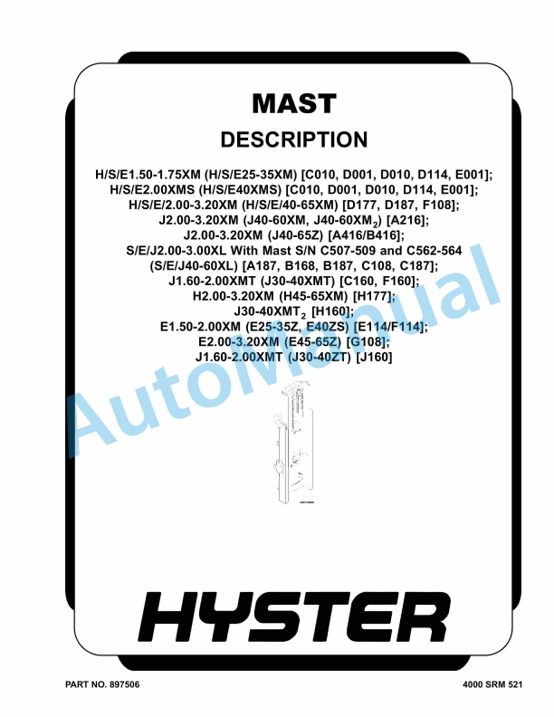
Hyster H-S-E1.50-1.75M to J1.60-2.00XMT Mast Description Maintenance And Repair
$30.00
- Type Of Manual: Maintenance And Repair
- Number of Pages: 904
- Size: 51.3MB
- Format: PDF
Description
-
Model List:
- H-S-E1.50-1.75XM, H-S-E2.00XMS, H-S-E-2.00-3.20XM, J2.00-3.20XM, J2.00-3.20XM, S-E-J2.00-3.00XL, J1.60-2.00XMT, H2.00-3.20XM, J30-40XMT2, E1.50-2.00XM, E2.00-3.20XM, J1.60-2.00XMT
- 1. RM0521-(03-2006)-UK-EN
- 1.1. Safety Precautions Maintenance and Repair
- 1.2. General
- 1.3. Description and Operation
- 1.4. Carriages
- 1.5. Mast Mounts
- 1.6. Two-Stage Mast, Limited Free-Lift (LFL)
- 1.7. Description and Operation
- 1.8. Two-Stage Mast, Full Free-Lift (FFL)
- 1.9. Description and Operation
- 1.10. Three-Stage Mast, Full Free-Lift (FFL)
- 1.11. Description and Operation
- 1.12. Four-Stage Mast
- 1.13. Description and Operation
- 1.14. Cylinder Cushion During Lifting Sequence
- 1.15. Cylinder Cushion During Lowering Sequence
- 2. RM0522-(07-2010)-UK-EN
- 2.1. Mast Repairs
- 2.2. Safety Precautions Maintenance and Repair
- 2.3. General
- 2.4. Safety Procedures When Working Near Mast
- 2.5. Fork Repair
- 2.6. Install
- 2.7. Carriages Repair
- 2.8. Standard Carriage, Remove
- 2.9. Hang-On Sideshift Carriage, Remove
- 2.10. Standard Carriage and Hang-On Sideshift Carriage, Repair
- 2.11. Standard Carriage, Install
- 2.12. Hang-On Sideshift Carriage, Install
- 2.13. Integral Sideshift Carriage
- 2.14. Clean and Inspect
- 2.15. Install
- 2.16. Mast Repair
- 2.17. Two-Stage LFL and Two-Stage FFL Masts, Disassemble
- 2.18. Three-Stage FFL Mast
- 2.19. Disassemble
- 2.20. Mast and Chains, Clean and Inspect
- 2.21. Two-Stage LFL and Two-Stage FFL Mast, Assemble
- 2.22. Three-Stage FFL Mast, Assemble
- 2.23. Install
- 2.24. Lift Cylinders Repair
- 2.25. Main Lift Cylinders, Remove
- 2.26. Free-Lift Cylinder, Remove
- 2.27. Cylinders, Disassemble
- 2.28. Two-Stage Full Free-Lift Mast, Right-Hand Main Lift Cylinder
- 2.29. Two-Stage Full Free-Lift Mast, Left-Hand Main Lift Cylinder
- 2.30. Two-Stage Limited Free-Lift Mast and Three-Stage Full Free-Lift
- 2.31. Two-Stage Limited Free-Lift Mast and Three-Stage Full Free-Lift
- 2.32. Two-Stage Full Free-Lift Mast and Three-Stage Full Free-Lift Mas
- 2.33. Clean and Inspect
- 2.34. Cylinders, Assemble
- 2.35. Two-Stage Full Free-Lift Mast, Right-Hand Main Lift Cylinder
- 2.36. Two-Stage Full Free-Lift Mast, Left-Hand Main Lift Cylinder
- 2.37. Two-Stage Limited Free-Lift Mast and Three-Stage Full Free-Lift
- 2.38. Two-Stage Limited Free-Lift Mast and Three-Stage Full Free-Lift
- 2.39. Two-Stage Full Free-Lift Mast and Three-Stage Full Free-Lift Mas
- 2.40. Main Lift Cylinders, Install
- 2.41. Free-Lift Cylinder, Install
- 2.42. Header Hose Arrangements
- 2.43. Two-Stage LFL Mast, New Hose Install
- 2.44. Two-Stage LFL Mast, Adjust Hoses After Installation
- 2.45. Two-Stage FFL Mast, New Hose Install
- 2.46. Two-Stage FFL Mast, Adjust Hoses After Installation
- 2.47. Three-Stage FFL Mast, New Hose Install
- 2.48. Three-Stage FFL Mast, Adjust Hoses After Installation
- 2.49. Header Hose Arrangement
- 2.50. Two-Stage LFL Mast, New Hose Install
- 2.51. Two-Stage LFL Mast, Adjust Hoses After Installation
- 2.52. Two-Stage FFL Mast, New Hose Install
- 2.53. Two-Stage FFL Mast, Adjust Hoses After Installation
- 2.54. Three-Stage FFL Mast, New Hose Install
- 2.55. Three-Stage FFL Mast, Adjust Hoses After Install
- 2.56. Lift and Tilt System Leak Check
- 2.57. Lift Cylinders Leak Check
- 2.58. Tilt Cylinders Leak Check
- 2.59. Tilt Cylinders Adjustment
- 2.60. Lift Chains Adjustment
- 2.61. Mast Adjustment
- 2.62. Carriage Adjustment
- 2.63. Troubleshooting
- 2.64. Table 1. Hook-Type Carriage Chain Adjustment
- 2.65. Table 2. Pin-Type Carriage Chain Adjustment
- 3. RM0103-(03-2007)-UK-EN
- 3.1. Tilt Cylinders
- 3.2. Safety Precautions Maintenance and Repair
- 3.3. General
- 3.4. Description
- 3.5. Tilt Cylinder Repair
- 3.6. Disassemble
- 3.7. Assemble
- 3.8. Tilt Cylinders With O-Ring or Single-Lip Seals
- 3.9. Tilt Cylinders for XM and XMS Models
- 3.10. Tilt Cylinders for XL, XLS, and XL 3 Models
- 3.11. Tilt Cylinders for H700-800A and Early Model H700-920B
- 3.12. Install
- 3.13. Tilt Cylinders Using Chevron Packing
- 3.14. Tilt Cylinder Leak Check
- 3.15. Tilt Cylinder Stroke and Mast Tilt Angle Adjustment
- 3.16. Torque Specifications
- 3.17. Piston Rod Nut
- 3.18. Retainer
- 3.19. Troubleshooting
- 3.20. Table 1. Movement Rates (Maximum) for Tilt Cylinders
- 4. RM0231-(01-2016)-UK-EN
- 4.1. General
- 5. RM1058-(04-2011)-UK-EN
- 5.1. Troubleshooting and Adjustments Using the AC Controls Program (E
- 5.2. Safety Precautions Maintenance and Repair
- 5.3. General
- 5.4. Computer Requirements
- 5.5. Software, Install
- 5.6. Language Selection
- 5.7. Demo Mode
- 5.8. Connect PC to Lift Truck
- 5.9. Starting AC Controls Program
- 5.10. Lift Truck Control Setup
- 5.11. Change Lift Truck Serial Number or Hourmeter
- 5.12. Setting Factory Default Values or Changing Lift Truck Parameters
- 5.13. Create New Custom Lift Truck Configuration
- 5.14. Lift Truck Configuration Properties
- 5.15. Import New Lift Truck Configuration From Disk
- 5.16. Delete Custom Lift Truck Configuration or Password File
- 5.17. Dash Display
- 5.18. Custom Display Languages
- 5.19. Download Display Language
- 5.20. Clear Operator Log
- 5.21. Password Functions
- 5.22. Enable/Disable Password and Lift Truck Inspection Functions
- 5.23. Truck Inspection Checklist
- 5.24. Password
- 5.25. Password Properties
- 5.26. Create New Password File
- 5.27. Download Passwords
- 5.28. Upload Passwords
- 5.29. Reports Menu
- 5.30. Devices Report
- 5.31. Custom Report
- 5.32. Password Report
- 5.33. Operator Report
- 5.34. Current Settings Report
- 5.35. Status Code Report
- 5.36. Status Codes Log
- 5.37. Troubleshooting
- 5.38. Diagnostics
- 5.39. Help Menu
- 5.40. General
- 5.41. Contents
- 5.42. Technical Support
- 5.43. About Electric Truck AC Controls Program
- 6. RM1073-(06-2004)-UK-EN
- 6.1. Safety Precautions Maintenance and Repair
- 6.2. Introduction
- 6.3. General
- 6.4. Description of Operation
- 6.5. Discharging the Capacitors
- 6.6. Covers and Floor Plates
- 6.7. Overhead Guard Repair
- 6.8. Install
- 6.9. Hood and Seat Assembly
- 6.10. Install
- 6.11. Counterweight
- 6.12. Install
- 6.13. Safety Labels
- 6.14. Painting Instructions
- 7. RM1074-(06-2004)-UK-EN
- 7.1. Transaxle
- 7.2. Safety Precautions Maintenance and Repair
- 7.3. Introduction
- 7.4. General
- 7.5. Discharging the Capacitors
- 7.6. Description
- 7.7. Transmission
- 7.8. Traction Motor
- 7.9. Maintenance
- 7.10. Oil Level Check
- 7.11. Oil Change
- 7.12. Transaxle Assembly
- 7.13. Disassemble
- 7.14. Traction Motor and Covers
- 7.15. Brake Assembly and Gears
- 7.16. Planetary Gears and Drive Axle
- 7.17. Clean and Inspect
- 7.18. Assemble
- 7.19. Planetary Gears and Drive Axle
- 7.20. Brake Assembly and Gears
- 7.21. Traction Motor and Covers
- 7.22. Install
- 7.23. Troubleshooting
- 7.24. Table 1. Special Tools
- 7.25. Table 2. Conventional Tools
- 8. RM1075-(02-2008)-UK-EN
- 8.1. Steering System
- 8.2. Safety Precautions Maintenance and Repair
- 8.3. Introduction
- 8.4. General
- 8.5. Discharging the Capacitors
- 8.6. Description of Operation
- 8.7. Steering Pressure Check
- 8.8. Operation Check
- 8.9. Steering Wheel and Column
- 8.10. Steering Column Covers
- 8.11. Install
- 8.12. Steering Column Components
- 8.13. Install
- 8.14. Steering Control Unit Assembly
- 8.15. Power Steering Pump and Motor
- 8.16. Description
- 8.17. Install
- 8.18. Disassemble
- 8.19. Assemble
- 8.20. Steering Actuator Components
- 8.21. Steer Tire and Wheel Assembly
- 8.22. Install
- 8.23. Wheel Hub Assembly
- 8.24. Install
- 8.25. Steering Axle Assembly
- 8.26. Install
- 8.27. Troubleshooting
- 9. RM1076-(03-2004)-UK-EN
- 9.1. Brake System
- 9.2. Safety Precautions Maintenance and Repair
- 9.3. Introduction
- 9.4. General
- 9.5. Discharging the Capacitors
- 9.6. Brake Pedal Assembly
- 9.7. Disassemble
- 9.8. Assemble
- 9.9. Install
- 9.10. Master Cylinder
- 9.11. Install
- 9.12. Adjustments
- 9.13. Bleed the Brake System
- 9.14. Adjust Linkage
- 9.15. Brake Lines
- 9.16. Parking Brake
- 9.17. Disassemble
- 9.18. Assemble
- 9.19. Install
- 9.20. Troubleshooting
- 10. RM1077-(09-2013)-UK-EN
- 10.1. Hydraulic System
- 10.2. Safety Precautions Maintenance and Repair
- 10.3. Introduction
- 10.4. General
- 10.5. Discharging the Capacitors
- 10.6. Hydraulic System
- 10.7. Hydraulic Oil
- 10.8. Hydraulic Lines
- 10.9. Cleaning
- 10.10. Sound Level
- 10.11. Maintenance
- 10.12. Hydraulic Oil Filter, Change
- 10.13. Hydraulic Oil Strainer, Check
- 10.14. Hydraulic Oil, Change
- 10.15. Hydraulic Tank Assembly
- 10.16. Trisodium Phosphate Method
- 10.17. Install
- 10.18. Lift Pump and Motor
- 10.19. Disassemble
- 10.20. Assemble
- 10.21. Install
- 10.22. Lift Pump
- 10.23. Disassemble
- 10.24. Assemble
- 11. RM1085-(03-2004)-UK-EN
- 11.1. HUSCO Main Control Valve
- 11.2. Safety Precautions Maintenance and Repair
- 11.3. General
- 11.4. Description
- 11.5. Operation
- 11.6. Lift Section
- 11.7. Tilt Section
- 11.8. Tilt Backward
- 11.9. Tilt Forward
- 11.10. Relief Valve
- 11.11. Main Control Valve Repair
- 11.12. Disassemble
- 11.13. Clean and Inspect
- 11.14. Assemble
- 11.15. Install
- 11.16. Pressure Relief Valve Check and Adjustment
- 11.17. Primary Relief Valve
- 11.18. Secondary Relief Valve
- 11.19. Troubleshooting
- 12. RM1086-(06-2004)-UK-EN
- 12.1. Electro-Hydraulic Control Valve
- 12.2. Safety Precautions Maintenance and Repair
- 12.3. General
- 12.4. Description
- 12.5. Electro-Hydraulic Control System
- 12.6. Electro-Hydraulic Control Valve
- 12.7. Valve Driver Module
- 12.8. Manual Lowering Valve
- 12.9. Hydraulic Lever Console
- 12.10. Electro-Hydraulic Control Valve
- 12.11. Disassemble
- 12.12. Clean and Inspect
- 12.13. Assemble
- 12.14. Lift Valve Section
- 12.15. Tilt/Auxiliary Valve Sections
- 12.16. Valve Spool Coils
- 12.17. Fittings
- 12.18. Install
- 12.19. Check and Adjust
- 12.20. Tilt Counterbalance Valve
- 12.21. Main Relief Valve
- 12.22. Auxiliary Relief Valve
- 12.23. Valve Driver Module
- 12.24. Install
- 12.25. Hydraulic Lever Console
- 12.26. Disassemble
- 12.27. Hydraulic Control Lever
- 12.28. Main PC Board
- 12.29. Assemble
- 12.30. Main PC Board
- 12.31. Hydraulic Control Lever
- 12.32. Install
- 12.33. Troubleshooting
- 12.34. Troubleshooting Chart
- 12.35. Table 1. Error Codes
- 13. RM1087-(09-2013)-UK-EN
- 13.1. AC Motor Controllers/Display Panel
- 13.2. Safety Precautions Maintenance and Repair
- 13.3. Description
- 13.4. General
- 13.5. Description
- 13.6. AC Motors
- 13.7. ZAPI AC Motor Controller
- 13.8. Principles of Operation
- 13.9. Controller Thermal Management
- 13.10. Controller Area Network (CANbus)
- 13.11. Discharging the Capacitors
- 13.12. AC Motor Controller Repair
- 13.13. General
- 13.14. Special Precautions
- 13.15. Thermal Sensors
- 13.16. Motor Controller, Replace
- 13.17. Controller Checks and Adjustments
- 13.18. Function Parameters
- 13.19. General
- 13.20. Function Parameter Descriptions
- 13.21. Parameters
- 13.22. Top Speed Forward
- 13.23. Top Speed Reverse
- 13.24. Acceleration
- 13.25. Regen Braking
- 13.26. Auto Deceleration
- 13.27. Extended Shift
- 13.28. Pump Acceleration
- 13.29. Tilt/Auxiliary Pump Acceleration
- 13.30. Low Lift Speed
- 13.31. Maximum Lift Speed
- 13.32. Maximum Lowering Speed
- 13.33. Tilt Speed
- 13.34. d Function
- 13.35. d Function Speed
- 13.36. h Function
- 13.37. h Function Speed
- 13.38. Battery Voltage
- 13.39. Lift Interrupt
- 13.40. BDI Adjustment (Early Models)
- 13.41. BDI Adjustment (Later Models)
- 13.42. BDI Decrement Time
- 13.43. Service Reminder
- 13.44. Restore Defaults
- 13.45. Calibration Parameters
- 13.46. Throttle Calibration
- 13.47. Steering Calibration
- 13.48. Display Panel
- 13.49. General
- 13.50. Premium Display Panel
- 13.51. Standard Display Panel
- 13.52. Display Functions and Features
- 13.53. Key-On Initialization
- 13.54. Standard Display
- 13.55. Premium Display
- 13.56. Lift Truck Inspection Function
- 13.57. Access to Service Functions
- 13.58. Service Functions
- 13.59. Performance Modes
- 13.60. Battery Discharge Indicator (BDI)
- 13.61. Hourmeter
- 13.62. Status Code List
- 13.63. Dash Display Service Menu Navigation
- 13.64. General
- 13.65. Moving Through Menu Selections
- 13.66. Editing and Adding Information
- 13.67. ETACC Test
- 13.68. Manual Hydraulics
- 13.69. Electro-Hydraulics
- 13.70. Troubleshooting
- 13.71. General
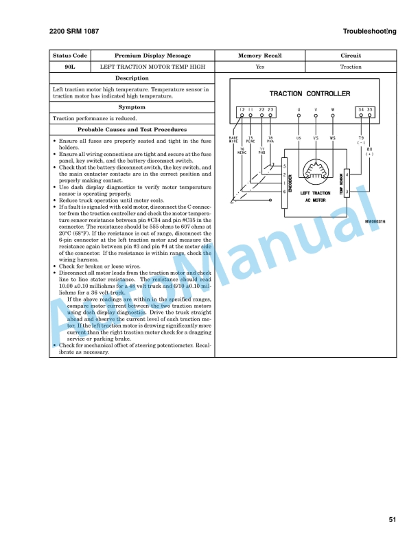
- 13.72. Status Codes
- 13.73. Controller Connector Pin Outs
- 13.74. Valve Driver Module (Electro-Hydraulic Valve Option)




%20Service%20Manual&url=https://pdfrepairmanual.com/docs/hyster-b160-j25-35bs-service-manual/&media=https://pdfrepairmanual.com/wp-content/uploads/2026/01/hyster-b160-j25-35bs-service-manual-1.jpg)

%20Service%20Manual&url=https://pdfrepairmanual.com/docs/hyster-b174-r30es-service-manual/&media=https://pdfrepairmanual.com/wp-content/uploads/2026/01/hyster-b174-r30es-service-manual-1.jpg)
%20Maintenance%20Schedule&url=https://pdfrepairmanual.com/docs/hyster-c098-e3-50-5-50xl-e4-50xls-maintenance-schedule/&media=https://pdfrepairmanual.com/wp-content/uploads/2026/01/hyster-c098-e350-550xl-e450xls-maintenance-schedule-1.jpg)
%20Service%20Manual&url=https://pdfrepairmanual.com/docs/hyster-c002-s30-50c-service-manual/&media=https://pdfrepairmanual.com/wp-content/uploads/2026/01/hyster-c002-s30-50c-service-manual-1.jpg)
%20Service%20Manual&url=https://pdfrepairmanual.com/docs/hyster-b418-p1-6-p1-8-p2-0-p2-2-service-manual/&media=https://pdfrepairmanual.com/wp-content/uploads/2026/01/hyster-b418-p16-p18-p20-p22-service-manual-1.jpg)
%20Service%20Manual&url=https://pdfrepairmanual.com/docs/hyster-c005-h60-90c-service-manual/&media=https://pdfrepairmanual.com/wp-content/uploads/2026/01/hyster-c005-h60-90c-service-manual-1.jpg)
%20Service%20Manual&url=https://pdfrepairmanual.com/docs/hyster-c098-e70-120xl-service-manual/&media=https://pdfrepairmanual.com/wp-content/uploads/2026/01/hyster-c098-e70-120xl-service-manual-1.jpg)
There are no reviews yet.