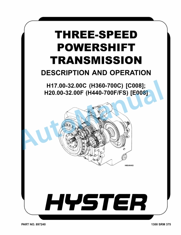
Hyster H17.00-32.00C, H20.00-32.00F Three-Speed Powershift Transmission Maintenance And Repair
$30.00
- Type Of Manual: Maintenance And Repair
- Number of Pages: 1039
- Size: 45.9MB
- Format: PDF
Description
-
Model List:
- H17.00-32.00C, H20.00-32.00F Three-Speed Powershift Transmission
- 1. RM0375-(07-2005)-UK-EN
- 1.1. Three-Speed Powershift Transmission
- 1.2. Safety Precautions Maintenance and Repair
- 1.3. General
- 1.4. Mechanical Description
- 1.5. General
- 1.6. Torque Converter
- 1.7. Description
- 1.8. Operation
- 1.9. Clutch Assemblies
- 1.10. Description
- 1.11. Operation
- 1.12. Forward Shaft
- 1.13. Reverse Shaft
- 1.14. First Speed Shaft
- 1.15. Output Shaft
- 1.16. Hydraulic Operation
- 1.17. Sump, Filter, and Pump
- 1.18. Shift Control Valve
- 1.19. Solenoid Valves
- 1.20. Inching Spool
- 1.21. Direction Spools
- 1.22. Range Spools
- 1.23. Modulator Valve and Manifold Block
- 1.24. Operation
- 1.25. Transmission Control System H17.00-32.00C (H370-700C)
- 1.26. Transmission Control System H20.00-32.00F (H440-700F) (without a
- 1.27. Transmission Control System H20.00-32.00F (with auto shift APC 1
- 1.28. Gear Selector
- 1.29. Hydraulic Circuits
- 1.30. Cooling and Lubrication
- 1.31. Operation of Transmission, Neutral
- 1.32. Operation of Transmission, Forward – First
- 1.33. Operation of Transmission, Reverse – First
- 1.34. Operation of Transmission, Forward – Second
- 1.35. Operation of Transmission, Forward – Third – Inching
- 1.36. Automatic Powershift Controller (APC 100)
- 1.37. General
- 1.38. Functional Descriptions
- 1.39. Automatic Shifting
- 1.40. Declutch Mode
- 1.41. Direction Change Inhibition
- 1.42. Downshift Inhibition
- 1.43. Drive Engagement Inhibition
- 1.44. Turbine (Output) Speed Sensor Signal Loss Warning
- 1.45. Parking Brake Mode
- 1.46. Speed Sensors
- 1.47. System Overview
- 1.48. Automatic/Manual (Pin 9)
- 1.49. Declutch (Pin 8)
- 1.50. Converter Temperature (Pin 7)
- 1.51. Engine Speed (Pins 28, 29)
- 1.52. Turbine (Output) Speed (Pins 30,31)
- 1.53. Parking Brake (Pin 25)
- 1.54. Throttle Switch (Pin 23)
- 1.55. Outputs
- 1.56. Diagnostic LEDs
- 1.57. Shift Solenoids (Pins 12, 13, 14, 15)
- 1.58. Transmission Warning Indicator (Pin 37)
- 1.59. Component Specifications
- 1.60. APC 100 Unit
- 1.61. Bypass Box and Bypass Plug
- 1.62. APC 100 Output Fuse
- 1.63. Remove and Install
- 1.64. Failure Modes
- 1.65. APC 100 Unit
- 1.66. Automatic/Manual (Pin 9)
- 1.67. Declutch (Pin 8)
- 1.68. Engine Speed (Pins 28, 29)
- 1.69. Gear Selection (Pins 1, 2, 20, 21)
- 1.70. Outputs
- 1.71. Output Speed (Pins 30, 31)
- 1.72. Parking Brake (Pin 25)
- 1.73. Throttle Switch (Pin 23)
- 1.74. Diagnostic Procedures
- 1.75. Checking Speed Sensor Circuit
- 1.76. Checking Turbine (Output) Speed Sensor Circuit
- 1.77. Checking Shift Solenoid Circuits
- 1.78. Table 1. Engine Speed Sensor Specifications
- 1.79. Table 2. Turbine (Output) Speed Sensor Specifications
- 1.80. Table 3. Shift Solenoid Output Logic
- 1.81. Table 4. APC 100 Pin Connections to Wiring Harness
- 2. RM0376-(09-1997)-UK-EN
- 2.1. Three-Speed Powershift Transmission
- 2.2. Safety Precautions Maintenance and Repair
- 2.3. General
- 2.4. Transmission Repair
- 2.5. Disassemble
- 2.6. Inspect
- 2.7. Assemble
- 2.8. Install
- 2.9. Modulator Valve and Manifold Block Repair
- 2.10. Disassemble
- 2.11. Clean and Inspect
- 2.12. Assemble
- 2.13. Install
- 2.14. Shift Control Valve Repair
- 2.15. Disassemble
- 2.16. Clean and Inspect
- 2.17. Assemble
- 2.18. Install
- 2.19. Oil Pump Repair
- 2.20. Disassemble
- 2.21. Clean and Inspect
- 2.22. Assemble and Install
- 2.23. Transmission Control Assembly Repair
- 2.24. H17.00-32.00C (H360-700C)
- 2.25. Remove and Disassemble
- 2.26. Assemble and Install
- 2.27. H20.00-32.00F (H440-700F/FS)
- 2.28. Remove and Disassemble
- 2.29. Assemble and Install
- 2.30. Torque Converter Stall Speed Check
- 2.31. Transmission Oil Pressure Check
- 2.32. Clutch and Pump Circuits Pressure Checks (Check Port 1)
- 2.33. Torque Converter Circuit Pressure Check (Check Port 2)
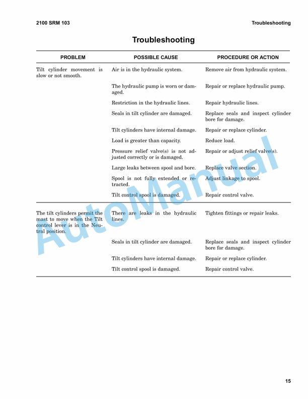
- 2.34. Troubleshooting
- 2.35. Table 1. Pressure Check Ports
- 3. RM0429-(04-1997)-UK-EN
- 3.1. INTRODUCTION
- 3.2. STEERING WHEEL AND COLUMN ASSEMBLY
- 3.3. STEERING CONTROL UNIT
- 3.4. FLOW AMPLIFIER
- 3.5. CHECKS AND ADJUSTMENTS
- 3.6. TROUBLESHOOTING
- 4. RM0472-(04-1992)-UK-EN
- 4.1. INTRODUCTION
- 4.2. REPAIRS
- 4.3. CHECKS AND ADJUSTMENTS
- 4.4. TROUBLESHOOTING
- 5. RM0486-(05-1992)-UK-EN
- 5.1. INTRODUCTION
- 5.2. REPAIRS
- 6. RM0487-(01-2010)-UK-EN
- 6.1. Periodic Maintenance
- 6.2. Safety Precautions Maintenance and Repair
- 6.3. General
- 6.4. Serial Number Data
- 6.5. How to Move Disabled Lift Truck
- 6.6. How to Tow Lift Truck
- 6.7. How to Put Lift Truck on Blocks
- 6.8. How to Raise Drive Tires
- 6.9. How to Raise Steering Tires
- 6.10. How to Clean a Lift Truck
- 6.11. Maintenance Schedule
- 6.12. Maintenance Procedures Every 8 Hours or Daily
- 6.13. How to Make Checks With Engine Stopped
- 6.14. Hydraulic System Oil
- 6.15. Engine Oil
- 6.16. Drive Belt
- 6.17. Cooling System
- 6.18. Battery
- 6.19. Air Filter
- 6.20. Fuel System
- 6.21. Water Separator (Fuel Filter)
- 6.22. Tires and Wheels
- 6.23. Forks, Mast, and Lift Chains, Inspect
- 6.24. Safety Labels
- 6.25. Operator Restraint System
- 6.26. How to Make Checks With Engine Running
- 6.27. Gauges, Lights, Horn, Fuses, Control Levers, and Pedals
- 6.28. Transmission Oil
- 6.29. Lift System Operation
- 6.30. Attachments
- 6.31. Hydraulic Oil Filters
- 6.32. Steering System
- 6.33. Maintenance Procedures Every 250 Hours or 2 Months
- 6.34. Engine Oil and Filter
- 6.35. Drive Shaft
- 6.36. Steering Axle
- 6.37. Lift Chains
- 6.38. Wear Check
- 6.39. Lubrication
- 6.40. Adjustments
- 6.41. Wheel Nuts
- 6.42. Hydraulic Tank Breathers
- 6.43. Air Filter, Heater
- 6.44. Drive Axle and Differential
- 6.45. Container Attachments
- 6.46. Drive Belt
- 6.47. Maintenance Procedures Every 500 Hours or 4 Months
- 6.48. Transmission Oil Filter
- 6.49. Fuel Filters
- 6.50. Coolant Filter
- 6.51. Maintenance Procedures Every 1000 Hours or 6 Months
- 6.52. Steer Wheel Bearing Nut
- 6.53. Transmission Oil
- 6.54. Other Lubrication
- 6.55. Fuel System
- 6.56. Idle Speed
- 6.57. Governed Speed
- 6.58. Maintenance Procedures Every 2000 Hours or Yearly
- 6.59. Hydraulic System
- 6.60. Steer Wheel Bearings
- 6.61. Drive Wheel Bearings
- 6.62. Differential and Drive Axle
- 6.63. Tilt Cab Operation
- 6.64. Raise Cab
- 6.65. Lower Cab
- 6.66. Fuel System Air Removal
- 6.67. Safety Procedures When Working Near Mast
- 6.68. Lift and Tilt System Leaks Check
- 6.69. Lift System
- 6.70. Tilt System
- 6.71. Wheels and Tires
- 6.72. Remove Wheels From Lift Truck
- 6.73. Remove Tire From Wheel
- 6.74. Install Wheel in Tire
- 6.75. Install Tire on Wheel
- 6.76. Add Air to Tires
- 6.77. Install Wheels
- 6.78. Table 1. Maintenance Schedule
- 6.79. Table 2. Maintenance Schedule, Container Attachments
- 6.80. Table 3. Steer Wheel Nut Torque Specifications
- 7. RM0488-(03-1992)-UK-EN
- 8. RM0489-(12-2009)-UK-EN
- 8.1. Capacities and Specifications
- 8.2. Safety Precautions Maintenance and Repair
- 8.3. Lift Truck Weights
- 8.4. Container Attachment Weights
- 8.5. Mast Speeds
- 8.6. Tier 2/3
- 8.7. Engine Specifications
- 8.8. Specifications
- 8.9. Capacities
- 8.10. Electrical System
- 8.11. Transmission Pressures
- 8.12. Torque Specifications
- 8.13. Brake System
- 8.14. Container Attachment
- 8.15. Differential
- 8.16. Drive Line and Axle
- 8.17. Hydraulic System Selector Valve
- 8.18. Mast and Carriages
- 8.19. Steering
- 8.20. Torque Converter
- 8.21. Transmission
- 9. RM0491-(04-1992)-UK-EN
- 9.1. INTRODUCTION
- 9.2. REPAIRS
- 9.3. CHECKS AND ADJUSTMENTS
- 9.4. TROUBLESHOOTING
- 10. RM0492-(03-2003)-UK-EN
- 10.1. Hydraulic System
- 10.2. Safety Precautions Maintenance and Repair
- 10.3. General
- 10.4. Description and Operation
- 10.5. Hydraulic Module
- 10.6. Main Control Valves
- 10.7. Remote Control Valve
- 10.8. Lift Manifold
- 10.9. Accumulator Charge Valve
- 10.10. Relief Valve and Pressure Reducing Valves
- 10.11. Directional Control Valve
- 10.12. Return Control Solenoid Valves
- 10.13. Carriage Solenoid Valves
- 10.14. Heat Exchanger System
- 10.15. Steering Control System
- 10.16. Brake System
- 10.17. Lift and Lower Circuit
- 10.18. Description
- 10.19. Operation
- 10.20. Lift Circuit, Normal Speed (Heavy Load)
- 10.21. Lift Circuit, High Speed (Light Load)
- 10.22. Two-Speed Cartridge
- 10.23. Lowering
- 10.24. Lowering Control Valves
- 10.25. Repairs
- 10.26. General
- 10.27. Hydraulic Module, Remove
- 10.28. Hydraulic Module, Install
- 10.29. Remote Control Valve
- 10.30. Main Control Valves
- 10.31. Lift Manifold
- 10.32. Checks and Adjustments
- 10.33. Pilot Pressure, Check
- 10.34. Main Control Valves Relief Pressure, Check
- 10.35. Two-Speed Cartridge, Check
- 10.36. Tilt Control Circuit
- 10.37. Description
- 10.38. Operation
- 10.39. Tilt Spool
- 10.40. Relief Valves in Main Control Valve
- 10.41. Relief Valves, Tilt Lock
- 10.42. Repairs
- 10.43. General
- 10.44. Relief Valves, Tilt Lock, Disassemble
- 10.45. Clean and Inspect
- 10.46. Checks and Adjustments
- 10.47. Main Control Valve Relief Pressure, Check
- 10.48. Flow Control Valves Repair
- 10.49. Description
- 10.50. Accumulator Charge Valve
- 10.51. Relief Valves
- 10.52. Pressure Reduction Valves
- 10.53. Repairs
- 10.54. Accumulator Charge Valve
- 10.55. Relief Valve
- 10.56. Pressure Reduction Valves
- 10.57. Checks and Adjustments
- 10.58. Relief Valves, Check and Adjust
- 10.59. Pressure Reduction Valves Check
- 10.60. Solenoid Valves Repair
- 10.61. Description
- 10.62. Directional Control Valve, Carriage/Attachment
- 10.63. Repairs
- 10.64. Directional Control Valve, Carriage/Attachment
- 10.65. Return Control Solenoid Valves
- 10.66. Return Control Solenoid
- 10.67. Carriage Solenoid Valves
- 10.68. Over Lowering Interrupt
- 10.69. Lift Interrupt
- 10.70. Checks and Adjustments
- 10.71. Torque Specifications
- 10.72. Control Valves
- 10.73. Remote Control Valve
- 10.74. Control Valve, Carriage/Attachment
- 10.75. Carriage Solenoid Valve
- 10.76. Specifications
- 10.77. Hydraulic Pump Output at 2500 rpm and 13.8 MPa ( 2000 psi)
- 10.78. Pressure Reduction Valves
- 10.79. Relief Pressures at 2500 rpm
- 10.80. Main Hydraulic Filters
- 10.81. Tank Capacity
- 10.82. Troubleshooting
- 10.83. Control Valves
- 10.84. Remote Control Valve
- 10.85. Flow Control Valves
- 10.86. Accumulator Charge Valve and Accumulator
- 10.87. Pressure Reduction Valve 2.1 MPa ( 300 psi)
- 10.88. Pressure Reduction Valve 10.3 MPa ( 1500 psi)
- 10.89. Solenoid Valves
- 10.90. Control Valve for Carriage and Attachment
- 10.91. Table 1. Accumulator Charge Valve Pressures
- 11. RM0626-(11-2001)-UK-EN
- 11.1. Cooling System
- 11.2. Safety Precautions Maintenance and Repair
- 11.3. General
- 11.4. Description
- 11.5. Radiator
- 11.6. Radiator Cap
- 11.7. Thermostat
- 11.8. Water Pump
- 11.9. Fan and Fan Shroud
- 11.10. Cooling System Checks
- 11.11. Radiator
- 11.12. Thermostat
- 11.13. Water Pump
- 11.14. Exhaust Leaks
- 11.15. Fan and Fan Shroud
- 11.16. Radiator Cleaning
- 11.17. Troubleshooting
- 12. RM0002-(01-2016)-UK-EN
- 12.1. General
- 12.2. Description
- 12.3. Alternator Repair
- 12.4. General Check and Adjustment
- 12.5. Low Output Check (Type A or Type B)
- 12.6. High Output Check (Type A or Type B)
- 12.7. Brushes Circuit Check
- 12.8. Diodes Check
- 12.9. Diode Bridge Check
- 12.10. Rotor Field Winding Check
- 12.11. Stator Windings Check
- 12.12. Voltage Regulator Check
- 12.13. Troubleshooting
- 13. RM0047-(10-2011)-UK-EN
- 13.1. Planetary Gear Axle
- 13.2. Safety Precautions Maintenance and Repair
- 13.3. General
- 13.4. Description
- 13.5. Operation
- 13.6. Planetary Gear Axle Repair
- 13.7. Disassemble
- 13.8. Planetary Axle, Disassemble
- 13.9. Assemble and Install
- 13.10. Planetary Axle, Assemble
- 13.11. Torque Specifications
- 13.12. Troubleshooting
- 13.13. Table 1. Axle-to-Frame Fasteners
- 13.14. Table 2. Standard Torque Values for Axle Fasteners
- 13.15. Table 3. Drive Wheel Nut Torque
- 14. RM0071-(03-2006)-UK-EN
- 14.1. Steering Axle
- 14.2. Safety Precautions Maintenance and Repair
- 14.3. General
- 14.4. Description
- 14.5. Steering Axle Repair
- 14.6. Install
- 14.7. Steering Cylinder Repair
- 14.8. Inspect
- 14.9. Assemble
- 14.10. Install
- 14.11. H7.00-12.50H (H150-275H), H13.50-16.00B (H300-350B), P7.00-9.00B
- 14.12. H360-620B Models
- 14.13. H16.00-30.00C (H360-650C), H20.00-32.00F (H440-700F/FS), and H36


%20Service%20Manual&url=https://pdfrepairmanual.com/docs/hyster-b210-n30ah-service-manual/&media=https://pdfrepairmanual.com/wp-content/uploads/2026/01/hyster-b210-n30ah-service-manual-1.jpg)
%20Service%20Manual&url=https://pdfrepairmanual.com/docs/hyster-c001-h25-35xl-service-manual/&media=https://pdfrepairmanual.com/wp-content/uploads/2026/01/hyster-c001-h25-35xl-service-manual-1.jpg)


%20Service%20Manual&url=https://pdfrepairmanual.com/docs/hyster-c001-h1-25-1-75xl-service-manual/&media=https://pdfrepairmanual.com/wp-content/uploads/2026/01/hyster-c001-h125-175xl-service-manual-1.jpg)
%20Service%20Manual&url=https://pdfrepairmanual.com/docs/hyster-a406-r1-4-r1-6-service-manual/&media=https://pdfrepairmanual.com/wp-content/uploads/2026/01/hyster-a406-r14-r16-service-manual-1.jpg)

%20Service%20Manual&url=https://pdfrepairmanual.com/docs/hyster-c002-s30-50c-service-manual/&media=https://pdfrepairmanual.com/wp-content/uploads/2026/01/hyster-c002-s30-50c-service-manual-1.jpg)
%20Service%20Manual&url=https://pdfrepairmanual.com/docs/hyster-c005-h60-90c-service-manual/&media=https://pdfrepairmanual.com/wp-content/uploads/2026/01/hyster-c005-h60-90c-service-manual-1.jpg)
%20Service%20Manual&url=https://pdfrepairmanual.com/docs/hyster-b174-r30es-service-manual/&media=https://pdfrepairmanual.com/wp-content/uploads/2026/01/hyster-b174-r30es-service-manual-1.jpg)
There are no reviews yet.