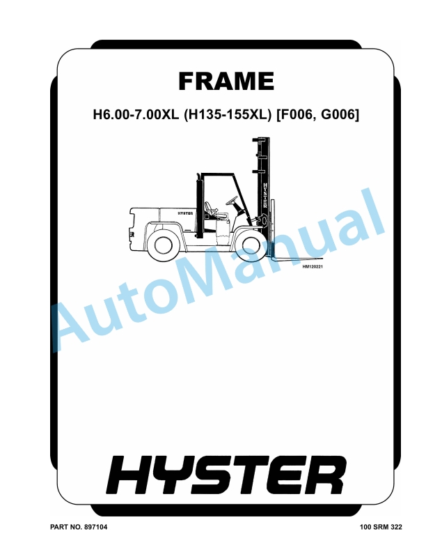
Hyster H6.00-7.00XL (H135-155XL) Frame Maintenance And Repair
$30.00
- Type Of Manual: Maintenance And Repair
- Number of Pages: 1324
- Size: 35.5MB
- Format: PDF
Description
-
Model List:
- H6.00-7.00XL (H135-155XL) Frame
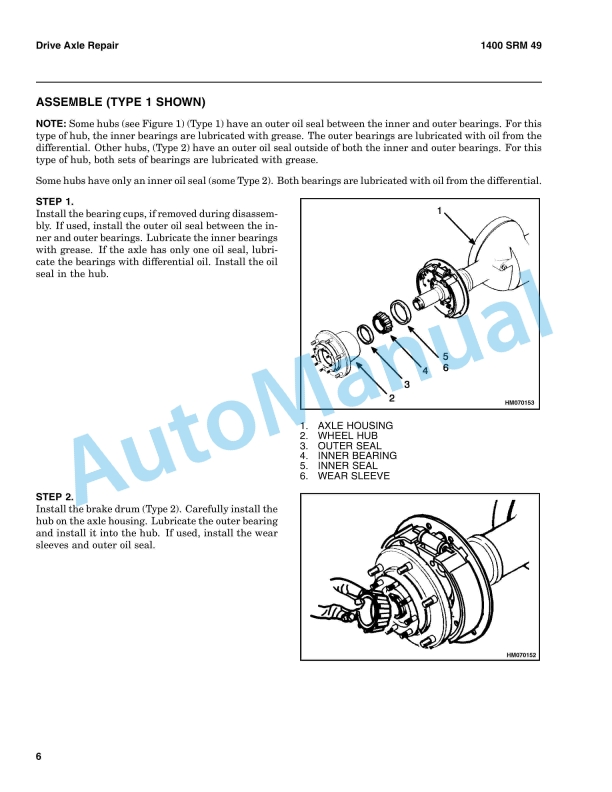
- 1. RM0322-(02-2007)-UK-EN
- 1.1. Safety Precautions Maintenance and Repair
- 1.2. General
- 1.3. Description
- 1.4. Counterweight Repair
- 1.5. Install
- 1.6. Hood Repair
- 1.7. Install
- 1.8. Overhead Guard Repair
- 1.9. Install
- 1.10. Operator Restraint System Repair
- 1.11. Automatic Locking Retractor (ALR)
- 1.12. Emergency Locking Retractor (ELR)
- 1.13. Hydraulic Tank Repair
- 1.14. Inspect
- 1.15. Small Leaks Repair
- 1.16. Large Leaks Repair
- 1.17. Steam Method
- 1.18. Chemical Solution Method
- 1.19. Other Methods of Preparation for Repair
- 1.20. Install
- 1.21. Fuel Tank Repair
- 1.22. Install
- 1.23. Radiator Repair
- 1.24. Install
- 1.25. Engine Repair
- 1.26. Install
- 1.27. Throttle Pedal Adjustment
- 1.28. Perkins 1104C-44(RE) Diesel Engine
- 1.29. Safety Labels
- 1.30. Cab Repair
- 1.31. Cab, Replace
- 1.32. Window, Replace
- 1.33. Windshield Wipers and Heater
- 1.34. Table 1. Material Specifications for Cab Windows
- 2. RM0324-(10-2003)-UK-EN
- 2.1. Two-Speed Powershift Transmission
- 2.2. Safety Precautions Maintenance and Repair
- 2.3. General
- 2.4. Mechanical Description
- 2.5. Torque Converter
- 2.6. Transmission Pump
- 2.7. Shaft Assemblies
- 2.8. Input Shaft
- 2.9. Forward Clutch Shaft
- 2.10. Clutch Assemblies
- 2.11. Countershaft
- 2.12. Output Shaft
- 2.13. Hydraulic Operation
- 2.14. Torque Converter
- 2.15. Seal Rings
- 2.16. Control Valve
- 2.17. System Pressure Regulator
- 2.18. Clutch Pressure Regulator
- 2.19. Torque Converter Regulator
- 2.20. Inching Spool
- 2.21. Direction Spool, Direction Control Lever
- 2.22. Direction Spool, MONOTROL Pedal
- 2.23. Range Spool
- 2.24. Drain Spool
- 2.25. Accumulator
- 2.26. Modulator Spool
- 2.27. Operation
- 2.28. Lubrication Circuit
- 2.29. MONOTROL Pedal
- 2.30. Oil Flow Diagrams
- 2.31. Neutral
- 2.32. Forward-Low
- 2.33. Forward-Low-Inching
- 2.34. Reverse-Low
- 3. RM0325-(10-2003)-UK-EN
- 3.1. Two-Speed Powershift Transmission
- 3.2. Safety Precautions Maintenance and Repair
- 3.3. General
- 3.4. Transmission Repair
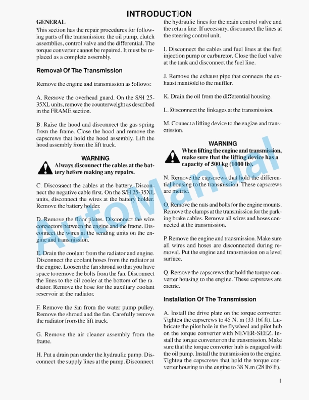
- 3.5. Transmission and Torque Converter, Remove
- 3.6. Transmission, Disassemble
- 3.7. Reverse-Low Clutch, Disassemble
- 3.8. Reverse-High Clutch, Disassemble
- 3.9. Forward-Low Clutch, Disassemble
- 3.10. Forward-High Clutch, Disassemble
- 3.11. Clean and Inspect
- 3.12. Forward Low and High Clutches Assembly
- 3.13. Forward Clutches, Assemble
- 3.14. Reverse-Low Clutch, Assemble
- 3.15. Reverse Clutches, Assemble
- 3.16. Transmission, Assemble
- 3.17. Torque Converter, Install
- 3.18. Control Valve Repair
- 3.19. Disassemble
- 3.20. Assemble
- 3.21. Install
- 3.22. MONOTROL Pedal
- 3.23. Remove and Disassemble
- 3.24. Assemble and Install
- 3.25. Stall Test
- 3.26. Linkage Adjustments
- 3.27. Linkage for Inching Pedal H6.00-7.00XL (H135-155XL, H135-155XL 2
- 3.28. Linkage for Inching Pedal S6.00-7.00XL (S135-155XL, S135-155XL 2
- 3.29. Linkage for Range Lever – Early Model H6.00-7.00XL (H135-155XL)
- 3.30. Linkage for Direction Control Lever – Early Model H6.00-7.00XL (
- 3.31. Linkage for Range Lever – Later Model H6.00-7.00XL (H135-155XL,
- 3.32. Linkage for Direction Control Lever – Later Model H6.00-7.00XL (
- 3.33. Linkage for Range Lever S6.00-7.00XL (S135-155XL, S135-155XL 2 )
- 3.34. Linkage for Direction Control Lever S6.00-7.00XL (S135-155XL, S1
- 3.35. Oil Pressure Check
- 3.36. System Pressure Check Port
- 3.37. Torque Converter Check Port
- 3.38. Clutch Pressure Check Port
- 3.39. Inching Pressure
- 3.40. Solenoid Check Ports (MONOTROL Control Only)
- 3.41. Lubrication Pressure Check Ports
- 3.42. Specifications
- 3.43. Troubleshooting
- 3.44. Correct System Pressure 1300 124 kPa ( 189 18 psi)
- 3.45. Correct Clutch Pressure 924 69 kPa ( 134 10 psi)
- 3.46. Correct Solenoid Pressure (MONOTROL Only) 965 138 kPa ( 140 2
- 3.47. Torque Converter Pressure 834 69 kPa ( 121 10 psi)
- 3.48. Lubrication Pressure 83 21 kPa ( 12 3 psi)
- 3.49. Table 1. Stall Speed Specifications
- 4. RM0326-(03-2007)-UK-EN
- 4.1. General
- 4.2. Description
- 4.3. Steering Axle Assembly Repair
- 4.4. Wheels and Hubs Repair (All Units)
- 4.5. Spindles and Bearings Repair (All Units)
- 4.6. Tie Rods Repair (All Units)
- 4.7. Steering Cylinder Repair
- 4.8. Troubleshooting
- 5. RM0327-(09-2003)-UK-EN
- 5.1. Brake System
- 5.2. Safety Precautions Maintenance and Repair
- 5.3. General
- 5.4. Description
- 5.5. Operation
- 5.6. Brake Booster and Master Cylinder
- 5.7. Brake Booster
- 5.8. Master Cylinder
- 5.9. Service Brake Assembly
- 5.10. Parking Brake
- 5.11. Brake Shoe Assemblies Repair
- 5.12. Remove and Disassemble
- 5.13. Clean and Inspect
- 5.14. Cleaning Procedures
- 5.15. Inspect
- 5.16. Assemble and Install
- 5.17. Master Cylinder Repair
- 5.18. Disassemble
- 5.19. Assemble
- 5.20. Install
- 5.21. Brake Booster Repair
- 5.22. Disassemble
- 5.23. Clean and Inspect
- 5.24. Assemble
- 5.25. Install
- 5.26. Brake System Air Removal
- 5.27. Brake Pedal Adjustment
- 5.28. Brake Shoes Adjustment
- 5.29. Parking Brake Adjustment
- 5.30. Parking Brake Switch Adjustment
- 5.31. Brake Booster Relief Valve Check
- 5.32. Troubleshooting
- 6. RM0328-(09-2003)-UK-EN
- 6.1. Hydraulic System
- 6.2. Safety Precautions Maintenance and Repair
- 6.3. General
- 6.4. Description and Operation
- 6.5. Hydraulic Pumps
- 6.6. Main Control Valve
- 6.7. Control Valve Lever
- 6.8. Steering Control Unit
- 6.9. Brake Valve
- 6.10. Oil Clutch, H6.00-7.00XL (H135-155XL) (F006)
- 6.11. Troubleshooting
- 6.12. Lift, Lower, and Tilt Circuit
- 6.13. Steering, Brake, and Oil Clutch System
- 7. RM0329-(09-2010)-UK-EN
- 7.1. Safety Precautions Maintenance and Repair
- 7.2. General
- 7.3. Description and Operation
- 7.4. General
- 7.5. Safety Procedures When Working Near Mast
- 7.6. Two-Stage Mast
- 7.7. Three-Stage Mast
- 7.8. Carriage Repair
- 7.9. Sideshift Carriage, Disassemble
- 7.10. Sideshift Carriage, Assemble
- 7.11. Install
- 7.12. Two-Stage Mast Repair
- 7.13. Disassemble
- 7.14. Clean and Inspect
- 7.15. Assemble
- 7.16. Install
- 7.17. Three-Stage Mast Repair
- 7.18. Disassemble
- 7.19. Clean and Inspect
- 7.20. Assemble
- 7.21. Install
- 7.22. Mast Operation Check
- 7.23. Lift and Tilt System Leaks Check
- 7.24. Lift System
- 7.25. Tilt System
- 7.26. Tilt Cylinder Stroke and Backward Tilt Angle Adjustment
- 7.27. Lift Chain Adjustments
- 7.28. Mast Adjustments
- 7.29. Carriage Adjustment
- 7.30. Troubleshooting
- 7.31. Table 1. Mast Parts Weight
- 7.32. Table 2. Hook-Type Carriage Chain Adjustment
- 7.33. Table 3. Pin-Type Carriage Chain Adjustment
- 8. RM0331-(09-2003)-UK-EN
- 8.1. Capacities and Specifications
- 8.2. Safety Precautions Maintenance and Repair
- 8.3. Lift Truck Weights
- 8.4. Capacities
- 8.5. Tire Sizes
- 8.6. Tire Pressure
- 8.7. Electrical System
- 8.8. Wheel Nut Torque
- 8.9. Engine Specifications
- 8.10. Hydraulic System
- 8.11. Mast Speeds
- 8.12. Transmission Oil Pressures
- 8.13. Torque Specifications
- 8.14. Engine – GM 4.3L V-6
- 8.15. Engine – Perkins 4.2482
- 8.16. Engine – Perkins 1004.4
- 8.17. Manual Transmission
- 8.18. Powershift Transmission
- 8.19. Speed Reducer
- 8.20. Drive Axle
- 8.21. Steering System
- 8.22. Brake System
- 8.23. Hydraulic System
- 8.24. Tilt Cylinder
- 9. RM0332-(09-1997)-UK-EN
- 9.1. ELECTRICAL SCHEMATIC (GASOLINE LPG)
- 9.2. ELECTRICAL SCHEMATIC (DIESEL, PERKINS 4.2482)
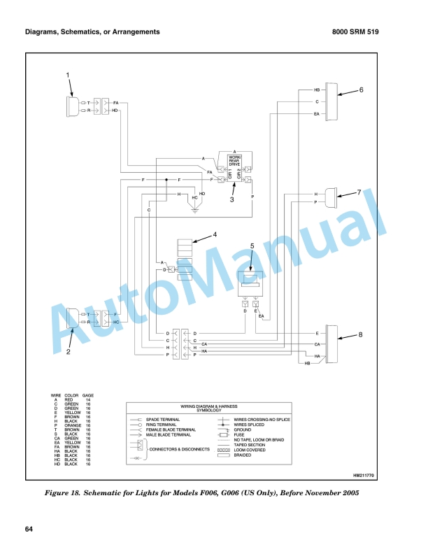
- 9.3. ELECTRICAL SCHEMATIC (DIESEL, PERKINS 1004.4)
- 9.4. HYDRAULIC SCHEMATIC
- 9.5. HYDRAULIC SCHEMATIC, POWERSHIFT TRANSMISSION WITH MANUAL CONTROL
- 9.6. HYDRAULIC SCHEMATIC, POWERSHIFT TRANSMISSION WITH MONOTROL PEDAL
- 10. RM0341-(06-2009)-UK-EN
- 10.1. Periodic Maintenance
- 10.2. Safety Precautions Maintenance and Repair
- 10.3. General
- 10.4. Serial Number Data
- 10.5. How to Move Disabled Truck
- 10.6. How to Tow Lift Truck
- 10.7. How to Put Lift Truck on Blocks
- 10.8. How to Raise Drive Tires
- 10.9. How to Raise Steering Tires
- 10.10. Maintenance Schedule
- 10.11. Maintenance Procedures Every 8 Hours or Daily
- 10.12. How to Make Checks With Engine Stopped
- 10.13. Hydraulic System Oil
- 10.14. Engine Oil
- 10.15. Drive Belts
- 10.16. Intake Manifold Rubber Cap
- 10.17. Cooling System
- 10.18. Air Filter
- 10.19. Fuel System
- 10.20. Primary Fuel Filter, Diesel Engine
- 10.21. Battery
- 10.22. Tires and Wheels
- 10.23. Forks, Mast, and Lift Chains, Inspect
- 10.24. Operator Restraint System
- 10.25. Safety Labels
- 10.26. How to Make Checks With Engine Running
- 10.27. Gauges, Lights, Horn, and Fuses
- 10.28. Oil Level, Powershift Transmission
- 10.29. Oil Level, Oil Clutch System, H3.50-5.00XL (H70-110XL)
- 10.30. Control Levers and Pedals
- 10.31. Lift System Operation
- 10.32. Inching/Brake Pedal
- 10.33. Service Brakes
- 10.34. Parking Brake
- 10.35. Steering System
- 10.36. Maintenance Procedures Every 250 Hours or 6 Weeks
- 10.37. Engine Oil and Filter, GM V-6 Engine
- 10.38. Lift Chains, Lubrication
- 10.39. Drive Shafts
- 10.40. Mast Lubrication
- 10.41. Crankcase Breather, GM V-6
- 10.42. Air Filter, GM V-6 EPA Compliant Engine
- 10.43. Maintenance Procedures Every 350 Hours or 2 Months
- 10.44. Engine Oil and Filter, Perkins 4.2482 Diesel Engine
- 10.45. Drive Belts
- 10.46. Perkins Diesel Engine
- 10.47. GM V-6 Engine (Early Models)
- 10.48. GM V-6 Engine (Late Models)
- 10.49. Brake Fluid
- 10.50. Lift Chains Wear Check
- 10.51. Forks Wear and Damage Check
- 10.52. Steering Axle Lubrication
- 10.53. Fuel System, Checks and Adjustments
- 10.54. Diesel Fuel System
- 10.55. LPG Carburetor (Early Models)
- 10.56. Gasoline Carburetor (Early Models)
- 10.57. Fuel Injection (Late Models)
- 10.58. Crankcase Breather, Perkins 4.2482 Diesel Engine
- 10.59. Hydraulic Tank Breather
- 10.60. Cooling System, Clean Debris from Radiator Core
- 10.61. Maintenance Procedures Every 500 Hours or 3 Months
- 10.62. Engine Oil and Filter, Perkins Diesel Engine
- 10.63. Crankcase Breather, Perkins Diesel Engine
- 10.64. PCV Valve, GM V-6
- 10.65. Maintenance Procedures Every 1000 Hours or 6 Months
- 10.66. Manifold Heat Valve, GM V-6 (Early Models)
- 10.67. Ignition System, GM V-6
- 10.68. Valve Clearance Adjustment
- 10.69. Fuel Filter, Replace (Diesel Engine)
- 10.70. Fuel System Air Removal (Perkins 1004-4 Diesel Engine)
- 10.71. Fuel Injection Pump With Vent Tube
- 10.72. Fuel Injection Pump With Vent Screw
- 10.73. Fuel System Air Removal (Perkins 4.2482 Diesel Engine)
- 10.74. Oil Level Check in Transmission
- 10.75. Manual Transmission, H3.50-5.00XL (H70-110XL)
- 10.76. Speed Reducer for Powershift Transmission, H3.50-5.00XL (H70-110
- 10.77. Manual Transmission, H6.00-7.00XL (H135-155XL)
- 10.78. Differential and Drive Axle for Powershift Transmission, H6.00-7
- 10.79. Differential, Speed Reducer, and Drive Axle for Manual Transmiss
- 10.80. Control Levers and Pedals, Lubricate
- 10.81. Crankcase Breather, Replace
- 10.82. Cooling System, GM V-6 EPA Compliant Engine
- 10.83. Spark Plug Replacement
- 10.84. Install
- 10.85. LPG Fuel Filter GM V-6 EPA Compliant Engine, Replace
- 10.86. Inspect Engine Electrical System, Connectors, and FCVS Connectio
- 10.87. Maintenance Procedures Every 2000 Hours or Yearly
- 10.88. Hydraulic System
- 10.89. Hydraulic Oil and Filter, H3.50-5.00XL (H70-110XL), Replace
- 10.90. Hydraulic Oil and Filter, H6.00-7.00XL (H135-155XL, H135-155XL 2
- 10.91. Oil Change and Oil Filter Replacement, Powershift Transmission,
- 10.92. Oil Change, Manual Transmission, H3.50-5.00XL (H70-110XL)
- 10.93. Oil Change, Manual Transmission, H6.00-7.00XL (H135-155XL)
- 10.94. Oil Change, Speed Reducer, Powershift Transmission, H3.50-5.00XL
- 10.95. Oil and Filter Change, Oil Clutch System, H3.50-5.00XL (H70-110X
- 10.96. Oil Change, Differential and Drive Axle, Powershift Transmission
- 10.97. Oil Change, Differential, Speed Reducer, and Drive Axle, Manual
- 10.98. Cooling System
- 10.99. PCV Valve, GM V-6
- 10.100. Service Brakes
- 10.101. LPG Filter, Replace
- 10.102. Gasoline Fuel Filter, Replace
- 10.103. Hood Latch Check, H3.50-5.00XL (H70-110XL)
- 10.104. Air Filter Element, GM V-6 EPA Compliant Engine
- 10.105. Oxygen Sensor GM V-6 EPA Compliant Engine
- 10.106. Inspect Low Pressure Regulator (LPR) for Oil Buildup and Leaks
- 10.107. Check Throttle Shaft for Sticking
- 10.108. Inspect Exhaust Manifold and Piping for Leaks
- 10.109. Test LPG/GAS Regulator Pressure
- 10.110. Safety Procedures When Working Near Mast
- 10.111. Lift Chain Adjustments
- 10.112. Fuel Injectors Repair
- 10.113. Lift and Tilt System Leak Check
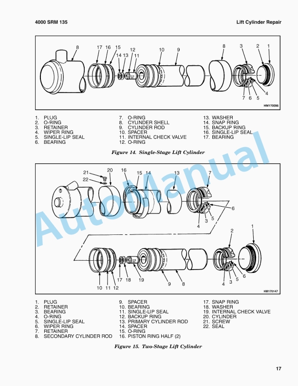
- 10.114. Lift Cylinders, Leak Check


%20Frame%20Maintenance%20And%20Repair&url=https://pdfrepairmanual.com/docs/hyster-h6-00-7-00xl-h135-155xl-frame-maintenance-and-repair/&media=https://pdfrepairmanual.com/wp-content/uploads/2026/01/hyster-h600-700xl-h135-155xl-frame-maintenance-and-repair-1.jpg)
%20Service%20Manual&url=https://pdfrepairmanual.com/docs/hyster-b174-r30es-service-manual/&media=https://pdfrepairmanual.com/wp-content/uploads/2026/01/hyster-b174-r30es-service-manual-1.jpg)
%20Service%20Manual&url=https://pdfrepairmanual.com/docs/hyster-b418-p1-6-p1-8-p2-0-p2-2-service-manual/&media=https://pdfrepairmanual.com/wp-content/uploads/2026/01/hyster-b418-p16-p18-p20-p22-service-manual-1.jpg)

%20Service%20Manual&url=https://pdfrepairmanual.com/docs/hyster-c007-h150-275hp150-200b-service-manual/&media=https://pdfrepairmanual.com/wp-content/uploads/2026/01/hyster-c007-h150-275hp150-200b-service-manual-1.jpg)
%20Service%20Manual&url=https://pdfrepairmanual.com/docs/hyster-b168-j2-00-3-00xl-service-manual/&media=https://pdfrepairmanual.com/wp-content/uploads/2026/01/hyster-b168-j200-300xl-service-manual-1.jpg)
%20Service%20Manual&url=https://pdfrepairmanual.com/docs/hyster-b160-j25-35bs-service-manual/&media=https://pdfrepairmanual.com/wp-content/uploads/2026/01/hyster-b160-j25-35bs-service-manual-1.jpg)
%20Service%20Manual&url=https://pdfrepairmanual.com/docs/hyster-c001-h25-35xl-service-manual/&media=https://pdfrepairmanual.com/wp-content/uploads/2026/01/hyster-c001-h25-35xl-service-manual-1.jpg)


There are no reviews yet.