
Description
-
Model List:
- Industrial Battery
- 1. RM0001-(03-2020)-UK-EN
- 1.1. General
- 1.2. Battery Type
- 1.2.1. Lead-Acid Batteries
- 1.2.2. Lithium-Ion Batteries
- 1.3. Specific Gravity
- 1.4. Chemical Reaction in a Cell
- 1.5. Electrical Terms
- 1.6. Battery Selection
- 1.7. Battery Voltage
- 1.8. Battery as a Counterweight
- 1.9. Battery Ratings
- 1.9.1. Kilowatt-Hours
- 1.10. Battery Maintenance
- 1.10.1. Safety Procedures
- 1.10.2. Maintenance Records
- 1.10.3. New Battery
- 1.10.4. Cleaning Battery
- 1.10.5. Adding Water to Battery
- 1.10.6. Hydrometer
- 1.10.7. Battery Temperature
- 1.10.8. Charging Battery
- 1.10.9. Where to Charge Batteries
- 1.10.10. Battery Connectors
- 1.10.11. Battery Care
- 1.11. Troubleshooting
- 2. RM0231-(10-2020)-UK-EN
- 2.1. General
- 2.1.1. Threaded Fasteners
- 2.1.2. Nomenclature, Threads
- 2.1.3. Strength Identification
- 2.1.4. Cotter (Split) Pins
- 2.1.5. Fastener Torque Tables
- 2.1.6. Conversion Table
- 3. RM1128-(07-2020)-UK-EN
- 3.1. Series Code / Model Designation Reference Table
- 3.2. General
- 3.3. Deutsch Crimping Tool
- 3.3.1. How to Strip a Wire for Use With Deutsch Crimping Tool
- 3.3.2. How to Crimp With the Deutsch Crimping Tool
- 3.3.3. Calibration Test for the Deutsch Crimping Tool
- 3.4. Deutsch Connectors
- 3.4.1. DT, DTM, and DTP Series Connectors
- 3.4.2. HD Series Connectors
- 3.5. Metri-Pack Connectors
- 3.5.1. Remove and Install
- 3.6. Micro-Pack Connectors
- 3.7. Weather-Pack Connectors
- 3.8. AMPSEAL Crimping Tools
- 3.8.1. AMP Hand Crimping Tool With Certi-Crimp
- 3.8.2. How to use AMP Hand Crimping Tool
- 3.8.3. AMP Pro-Crimper II Tool
- 3.8.4. How to Use AMP PRO-CRIMPER II Tool
- 3.9. AMPSEAL Connector Assemblies
- 3.9.1. Description for Plug Connector Assembly
- 3.9.2. Description for Plug Connector and Header Assembly
- 3.10. AMP Superseal 1.5 Crimping Tools
- 3.10.1. Mini Mic Receptacle and Tab Contacts
- 3.10.2. AMP Hand Application Tool
- 3.10.3. How to Use AMP Hand Application Tool
- 3.10.4. AMP Pro-Crimper II Tool
- 3.10.5. How to Use Pro-Crimper II Tool
- 3.11. AMP Superseal 1.5 Connector Assemblies
- 3.11.1. Description
- 3.11.2. Repair and Maintenance
- 3.11.3. Panel Mount Option
- 3.12. AMP Fastin-Faston Hand Tools
- 3.12.1. Description – AMP Double Action Hand Tool
- 3.12.2. Maintenance and Inspection Procedures
- 3.12.3. How to Use AMP Double Action Hand Tool
- 3.12.4. Description – AMP Extraction Tool
- 3.12.5. Maintenance and Inspection
- 3.12.6. How to Use AMP Extraction Tool
- 3.13. AMP Fastin-Faston Receptacles and Housings
- 3.13.1. Description
- 3.14. Wire Repair
- 3.14.1. Wire Splicing Requirements
- 3.14.2. Deutsch Jiffy Splice
- 3.15. Twisted/Shielded Cable and Leads Repair
- 3.16. Special Tools
- 4. RM1335-(07-2020)-UK-EN
- 4.1. General
- 4.1.1. Description
- 4.1.2. Display Panel Menu Access
- 4.2. Menu Flowchart
- 4.2.1. Supervisor Menu Flowchart
- 4.3. Menu Navigation
- 4.4. Icon Glossary
- 4.4.1. Introduction
- 4.4.2. Soft Key Icons
- 4.4.3. Overlay Icons
- 4.4.4. Icons on System Off Screen and Alert Screens
- 4.4.5. Main Menu Title Screens
- 4.4.6. Submenu Icons Grouped by Menu
- 4.5. Operating Screen
- 4.5.1. Introduction
- 4.5.2. Performance Mode Controls
- 4.5.3. Status and Warning Icons
- 4.5.4. Battery Discharge Indicator
- 4.5.5. Direction and Parking Brake Indicators
- 4.5.6. Hazard Flashers and Lighting Controls
- 4.5.7. Steer Angle Indicator
- 4.5.8. System Time
- 4.5.9. Load Weight Indicator
- 4.6. System Off/Alert Screens
- 4.6.1. Introduction
- 4.6.2. System Off Screen
- 4.6.3. Alert Screens
- 4.7. Password Screen
- 4.7.1. Introduction
- 4.7.2. Password Screen
- 4.7.3. Adding/Removing/Changing Passwords
- 4.7.4. Password Log
- 4.8. Activity Log Menu
- 4.8.1. Introduction
- 4.8.2. Operator Checklist Log
- 4.8.3. Password Log
- 4.8.4. Impact Events Log
- 4.9. Calibration Menu
- 4.9.1. Introduction
- 4.9.2. Load Weight Calibration
- 4.9.3. Return to Set Tilt Stop Point Calibration
- 4.9.4. E-Hydraulic and Manual Valve Threshold Calibration
- 4.9.5. Steering Wheel Center Point Calibration
- 4.9.6. Steer Axle Position Calibration
- 4.9.7. Steer Axle Center Point Calibration
- 4.9.8. Manual Hydraulics Calibration
- 4.10. Display Menu
- 4.10.1. Introduction
- 4.10.2. Set Date and Time Format Menu
- 4.10.3. Set Daylight Saving Time Menu
- 4.10.4. Set Time and Date Menu
- 4.10.5. Set Units Menu
- 4.11. Status Menu
- 4.11.1. Introduction
- 4.11.2. VSM Versions
- 4.11.3. Display Versions
- 4.11.4. Truck Serial Number
- 4.11.5. Hour Meters
- 4.11.6. E-Hydraulic Controller Versions
- 4.11.7. Pump Motor Controller Versions
- 4.11.8. Traction Motor Controller 1 Versions
- 4.11.9. Traction Motor Controller 2 Versions
- 4.11.10. Light Controller Versions
- 4.11.11. Impact Sensor Versions
- 4.12. Truck Setup Menu
- 4.12.1. Introduction
- 4.12.2. Add/Remove Password
- 4.12.3. Battery Settings
- 4.12.4. Restore Default Settings
- 4.12.5. Motion Alarm
- 4.12.6. Impact Monitor Settings
- 4.12.7. Auto Power-Off Time Delay
- 4.12.8. Return to Set Tilt
- 4.12.9. Traction Speed Limit
- 4.12.10. Scheduled Maintenance Reminder
- 4.12.11. Minimum Pump Standby Flow Rate
- 4.12.12. Operator Checklist
- 4.12.13. Impact Monitor Shutdown
- 4.12.14. Motor Braking
- 4.12.15. Steering Wheel Friction and Steering Turns Adjustment
- 5. RM1336-(07-2020)-UK-EN
- 5.1. General
- 5.1.1. Description
- 5.1.2. Display Panel Menu Access
- 5.2. Menu Flowchart
- 5.2.1. Technician Menu Flowchart
- 5.3. Menu Navigation
- 5.4. Icon Glossary
- 5.4.1. Introduction
- 5.4.2. Soft Key Icons
- 5.4.3. Overlay Icons
- 5.4.4. Heat Exchange Module Warning Indicator Screen
- 5.4.5. System Off Screen and Alert Screens
- 5.4.6. Main Menu Title Screens
- 5.4.7. Submenu Icons Grouped by Menu
- 5.5. Operating Screen
- 5.5.1. Introduction
- 5.5.2. Performance Mode Controls
- 5.5.3. Status and Warning Icons
- 5.5.4. Battery Discharge Indicator
- 5.5.5. Direction and Parking Brake Indicators
- 5.5.6. Hazard Flashers and Lighting Controls
- 5.5.7. Steer Angle Indicator
- 5.5.8. System Time
- 5.5.9. Load Weight Indicator
- 5.6. System Off/Alert Screens
- 5.6.1. Introduction
- 5.6.2. System Off Screen
- 5.6.3. Alert Screens
- 5.7. Password Screen
- 5.7.1. Introduction
- 5.7.2. Password Screen
- 5.7.3. Adding/Removing/Changing Passwords
- 5.7.4. Password Log
- 5.8. Activity Log Menu
- 5.8.1. Introduction
- 5.8.2. Operator Checklist Log
- 5.8.3. Password Log
- 5.8.4. Impact Events Log
- 5.9. Calibration Menu
- 5.9.1. Introduction
- 5.9.2. Load Weight Calibration
- 5.9.3. Return to Set Tilt Stop Point Calibration
- 5.9.4. E-Hydraulic and Manual Valve Threshold Calibration
- 5.9.5. Steering Wheel Center Point Calibration
- 5.9.6. Steer Axle Position Calibration
- 5.9.7. Steer Axle Center Point Calibration
- 5.9.8. Manual Hydraulics Calibration
- 5.10. Display Menu
- 5.10.1. Introduction
- 5.10.2. Set Date and Time Format Menu
- 5.10.3. Set Daylight Saving Time Menu
- 5.10.4. Set Time and Date Menu
- 5.10.5. Set Units Menu
- 5.11. Status Menu
- 5.11.1. Introduction
- 5.11.2. VSM Versions
- 5.11.3. Display Versions
- 5.11.4. Truck Serial Number
- 5.11.5. Hour Meters
- 5.11.6. E-Hydraulic Controller Versions
- 5.11.7. Pump Motor Controller Versions
- 5.11.8. Traction Motor Controller 1 Versions
- 5.11.9. Traction Motor Controller 2 Versions
- 5.11.10. Light Controller Versions
- 5.11.11. Impact Sensor Versions
- 5.11.12. E-Steer Controller 1 Versions
- 5.11.13. E-Steer Controller 2 Versions
- 5.12. Truck Setup Menu
- 5.12.1. Introduction
- 5.12.2. Add/Remove Password
- 5.12.3. Battery Settings
- 5.12.4. Motor Braking
- 5.12.5. Battery Mode
- 5.12.6. Battery Setup
- 5.12.7. BDI Adjustment Setting
- 5.12.8. Acceleration Rates
- 5.12.9. Hour Meter Initialization
- 5.12.10. Impact Monitor Shutdown
- 5.12.11. Operator Checklist
- 5.12.12. Minimum Pump Standby Flow Rate
- 5.12.13. Scheduled Maintenance Reminder
- 5.12.14. Traction Speed Limit
- 5.12.15. Return to Set Tilt
- 5.12.16. Auto Power-Off Time Delay
- 5.12.17. Impact Monitor Settings
- 5.12.18. Motion Alarm
- 5.12.19. Lift Hydraulic Function Maximum Speed and Ramp Times
- 5.12.20. Lower Hydraulic Function Maximum Speed and Ramp Times
- 5.12.21. Tilt Forward Hydraulic Function Maximum Speed and Ramp Times
- 5.12.22. Tilt Backward Hydraulic Function Maximum Speed and Ramp Times
- 5.12.23. Auxiliary 1A Hydraulic Function Maximum Speed and Ramp Times
- 5.12.24. Auxiliary 1B Hydraulic Function Maximum Speed and Ramp Times
- 5.12.25. Auxiliary 2A Hydraulic Function Maximum Speed and Ramp Times
- 5.12.26. Auxiliary 2B Hydraulic Function Maximum Speed and Ramp Times
- 5.12.27. Optional Hydraulic Functions
- 5.12.28. Rear Lights Control
- 5.12.29. Restore Default Settings
- 5.12.30. Steering Wheel Friction and Steering Turns Adjustment
- 5.13. Diagnostics Menu
- 5.13.1. Introduction
- 5.13.2. Fault Code Log
- 5.13.3. Speedometer
- 5.13.4. Direction Switch
- 5.13.5. Traction Motor 1 Status
- 5.13.6. Traction Motor 2 Status
- 5.13.7. Occupancy Sensor
- 5.13.8. Brake System Sensors
- 5.13.9. Pump Status
- 5.13.10. Hydraulic Control Inputs
- 5.13.11. E-Hydraulic Valves
- 5.13.12. Hydraulic Sensors
- 5.13.13. System Voltages
- 5.13.14. Steering Position Sensors
- 5.13.15. E-Steering Position Sensors
- 5.13.16. Electric Brake
- 6. RM1377-(09-2019)-UK-EN
- 6.1. SECTION 9010 Operational Diagnostic Procedures
- 6.1.1. Group 05 – Operational Checkout
- 6.2. SECTION 9025 Traction Motor
- 6.2.1. Group 10 – Principles of Operation
- 6.2.2. Group 30 – Observed Symptoms
- 6.3. SECTION 9030 Electrical System
- 6.3.1. Group 03 – General Maintenance and Diagnostic Data
- 6.3.2. Group 10 – Principles of Operation
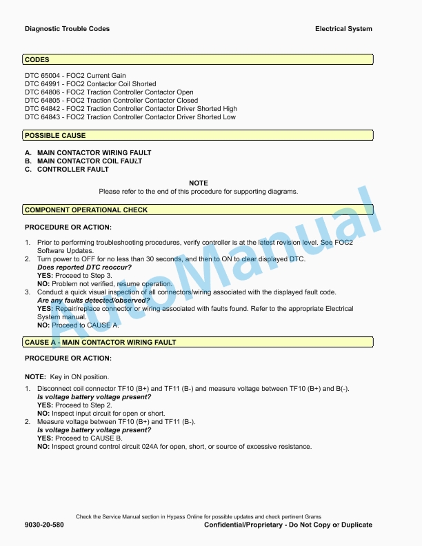
- 6.3.3. Group 20 – Diagnostic Trouble Codes
- 6.3.4. Group 30 – Observed Symptoms
- 6.3.5. Group 55 – Icons and Graphics
- 6.4. SECTION 9035 Drive Axle/Unit
- 6.4.1. Group 10 – Principles of Operation
- 6.4.2. Group 30 – Observed Symptoms
- 6.5. SECTION 9050 Hydraulic Systems
- 6.5.1. Group 10 – Principles of Operation
- 6.5.2. Group 33 – Observed Symptoms-Gear Pump
- 6.5.3. Group 43 – Tests and Adjustments-Gear Pump
- 6.6. SECTION 9060 Operators Station
- 6.6.1. Group 10 – Principles of Operation
- 6.7. SECTION 9070 Front End (Mast) and Chassis
- 6.7.1. Group 10 – Principles of Operation
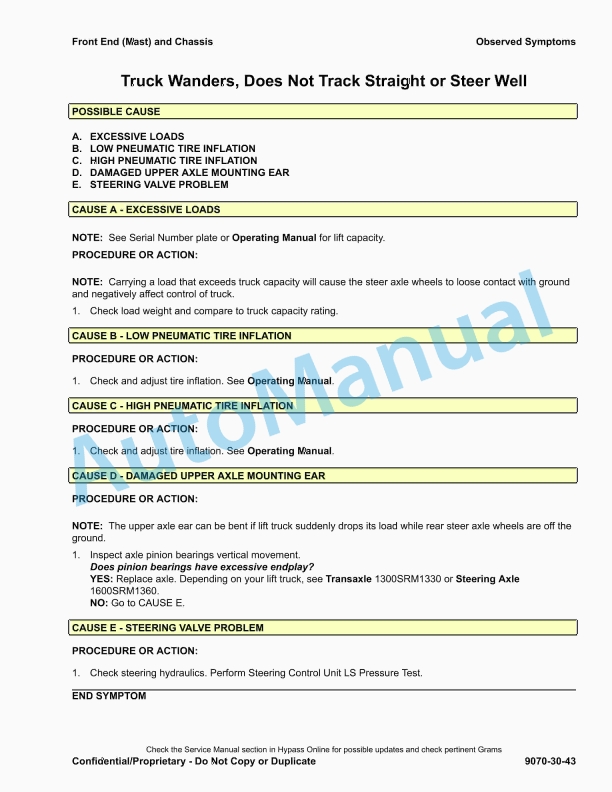
- 6.7.2. Group 30 – Observed Symptoms
- 6.8. SECTION 9080 Supplementary Data
- 6.8.1. Group 50 – Abbreviations and Acronyms
- 7. RM1446-(09-2014)-UK-EN
- 8. RM1514-(12-2013)-UK-EN
- 9. RM1515-(12-2013)-UK-EN
- 10. RM1516-(12-2013)-UK-EN
- 11. RM1517-(12-2013)-UK-EN
- 12. RM1518-(12-2013)-UK-EN
- 13. RM1519-(05-2014)-UK-EN
- 14. RM1520-(05-2014)-UK-EN
- 15. RM1521-(11-2015)-UK-EN
- 15.1. Safety Procedures When Working Near Mast
- 15.2. General
- 15.3. Description
- 15.4. Tilt Cylinder Repair
- 15.4.1. Disassemble
- 15.4.2. Inspect
- 15.4.3. Assemble
- 15.4.4. Install
- 15.4.5. Tilt Cylinders, Adjust
- 15.4.6. Tilt Cylinders Leak Check
- 15.5. Lift Cylinder Repair
- 15.5.1. Main Lift Cylinder (Mast a270, a271 and a272)
- 15.5.2. Main Lift Cylinder (Mast c662)
- 15.6. Free Lift Cylinder Repair
- 15.6.1. Free-Lift Cylinder (Mast a271 and a272)
- 15.6.2. Free-Lift Cylinder (Mast c662)
- 15.7. Sideshift Cylinder Repair
- 15.7.1. Disassemble
- 15.7.2. Clean and Inspect
- 15.7.3. Assemble and Install
- 15.8. Seal Kit Installation
- 15.8.1. External Installation (Seal and Back-Up Ring)
- 15.8.2. Internal Installation (Piston Rod Assembly)
- 15.9. Torque Specifications
- 15.9.1. Tilt Cylinders
- 15.9.2. Main and Free-Lift Cylinders
- 15.9.3. Sideshift Cylinder
- 16. RM1524-(01-2020)-UK-EN
- 16.1. General
- 16.1.1. Discharging the Capacitors
- 16.2. Display Panel and Key or Keyless Switch Replacement
- 16.2.1. Display Panel, Replace
- 16.3. Electronic and Manual Hydraulic Controls
- 16.3.1. General
- 16.3.2. Manual Hydraulic Controls
- 16.3.3. E-Hydraulic Controls – Test
- 16.3.4. E-Hydraulic Controls
- 16.4. Electronic-Hydraulic Controls, After January, 2020
- 16.4.1. General
- 16.4.2. E-Hydraulic Controls – TEST
- 16.4.3. Mini-levers, Remove and Install
- 16.4.4. Armrest Assembly
- 16.4.5. Horn Button
- 16.4.6. Direction Control Switch
- 16.4.7. Emergency Disconnect Switch
- 16.4.8. push (override) button
- 16.5. Sensors and Switches
- 16.5.1. General
- 16.5.2. Hydraulic Motor Speed Sensor
- 16.5.3. Hydraulic Motor Temperature Sensor
- 16.5.4. Traction Motor Temperature Sensor
- 16.5.5. Traction Motor Speed Sensor
- 16.5.6. Low Level Brake Fluid Switch
- 16.5.7. Service Brake Pressure Sensor
- 16.5.8. Accelerator Pedal Position Sensor

%20Service%20Manual&url=https://pdfrepairmanual.com/docs/hyster-c007-h150-275hp150-200b-service-manual/&media=https://pdfrepairmanual.com/wp-content/uploads/2026/01/hyster-c007-h150-275hp150-200b-service-manual-1.jpg)

%20Service%20Manual&url=https://pdfrepairmanual.com/docs/hyster-c098-e3-50-5-50xl-service-manual/&media=https://pdfrepairmanual.com/wp-content/uploads/2026/01/hyster-c098-e350-550xl-service-manual-1.jpg)
%20Service%20Manual&url=https://pdfrepairmanual.com/docs/hyster-c001-h1-25-1-75xl-service-manual/&media=https://pdfrepairmanual.com/wp-content/uploads/2026/01/hyster-c001-h125-175xl-service-manual-1.jpg)
%20Maintenance%20Schedule&url=https://pdfrepairmanual.com/docs/hyster-c098-e3-50-5-50xl-e4-50xls-maintenance-schedule/&media=https://pdfrepairmanual.com/wp-content/uploads/2026/01/hyster-c098-e350-550xl-e450xls-maintenance-schedule-1.jpg)

%20Service%20Manual&url=https://pdfrepairmanual.com/docs/hyster-c005-h60-90c-service-manual/&media=https://pdfrepairmanual.com/wp-content/uploads/2026/01/hyster-c005-h60-90c-service-manual-1.jpg)


%20Service%20Manual&url=https://pdfrepairmanual.com/docs/hyster-a406-r1-4-r1-6-service-manual/&media=https://pdfrepairmanual.com/wp-content/uploads/2026/01/hyster-a406-r14-r16-service-manual-1.jpg)
There are no reviews yet.