
Description
-
Model List:
- D375A-5E0 Bull Dozer
- 1. COVER
- 2. Preface
- 3. CONTENTS
- 4. Specifications
- 5. Precautions for field assembly
- 6. Disposal of removed parts
- 7. Assembly procedure, necessary equipment, and schedule
- 8. Layout of kit
- 9. Style for transportation
- 10. Table of tools for field assembly
- 11. Tightening torque
- 12. Coating materials list
- 13. Selection of wire ropes used for assembly
- 13.1. Assembly procedure
- 13.1.1. A1 Installation of chassis
- 13.1.2. A2.1 Installation of engine air inlet hood
- 13.1.3. A2.2 Installation of engine air precleaner (if equipped)
- 13.1.4. A3 Installing direction of exhaust pipe
- 13.1.5. A4 Installation of undercover
- 13.1.6. A5 Installation of pivot shaft
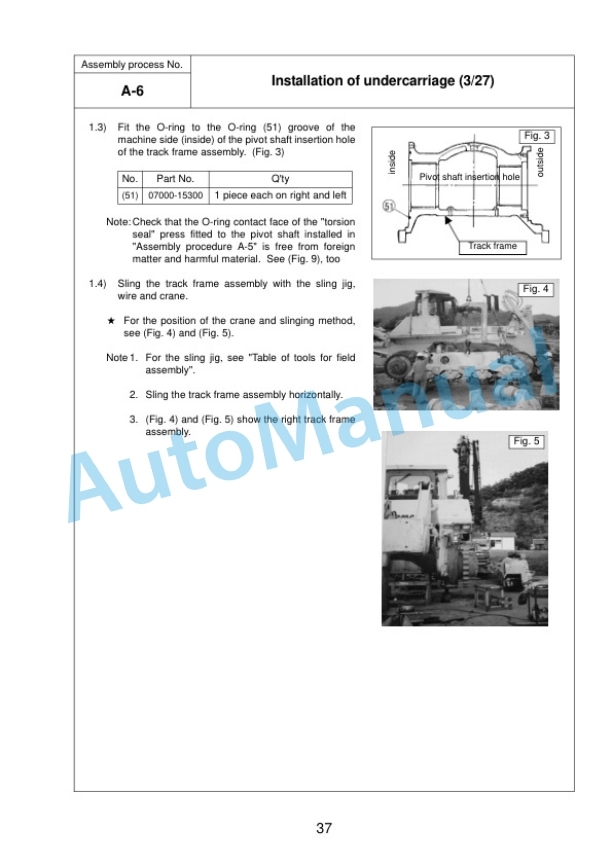
- 13.1.7. A6 Installation of undercarriage
- 13.1.8. A7 Adding oil to recoil chamber and pivot chamber
- 13.1.9. A8 Installation of blade lift cylinder
- 13.1.10. A9 Check fuel, coolant and lubricants
- 13.1.11. A10 Noinjection cranking of engine
- 13.1.12. A11 Bleeding air from hydraulic cylinders
- 13.1.13. A12 Installation of ripper
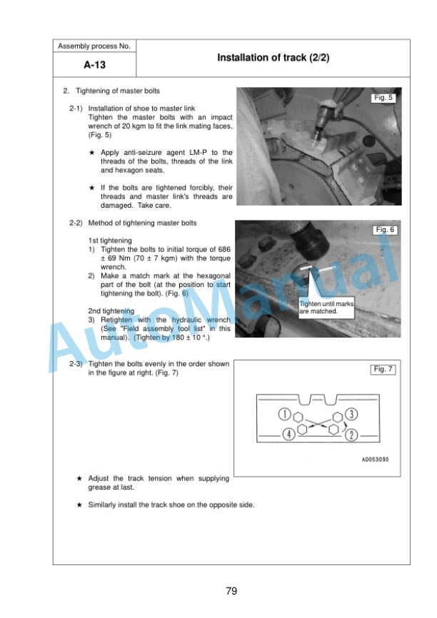
- 13.1.14. A13 Installation of track
- 13.1.15. A14 Assembly of blade
- 13.1.16. A15 Installation of blade
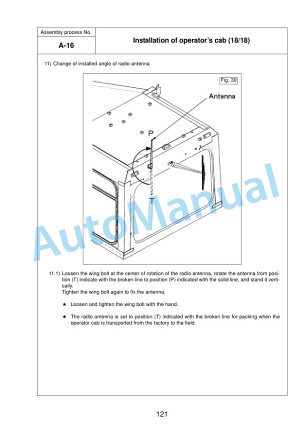
- 13.1.17. A16 Installation of operators cab
- 13.1.18. A17 Installation of ROPS
- 13.1.19. A18 Installation of VHMS, ORBCOMM antenna
- 13.1.20. A19Check track tension
- 13.1.21. A20Lubricating
- 13.1.22. A21 Installation of fuel quick charge piping (if equipped)
- 13.2. Check and maintenance proceduresafter completion of assembly
- 13.2.1. M1Check and adjustment of operators cab
- 13.2.2. M2Inspection of machine monitor
- 13.2.3. M3Checking operation of dual tilt mechanism (If equipped)
- 13.2.4. M4Setting procedure for USER ADJUST MODE
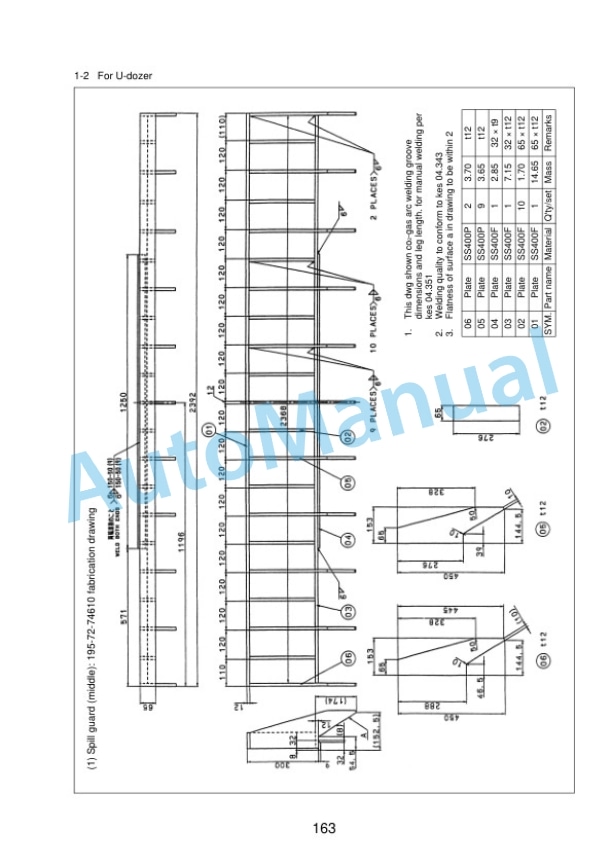
- 14. APPENDIX 1.Installation procedure for spill guard (Installation by welding)
- 15. APPENDIX 2. PRECAUTIONS FOR INITIALIZATION PROCEDURESFOR VHMS CONTROLLER
- 16. Field assembly inspection report



There are no reviews yet.