
Description
-
Model List:
- D475A-5 Bull Dozer
- 1. COVER
- 2. Preface
- 3. CONTENTS
- 4. SPECIFICATIONS
- 5. PRECAUTIONS FOR FIELD ASSEMBLY
- 6. ASSEMBLY PROCEDURE, NECESSARY EQUIPMENT, AND SCHEDULE
- 7. LAYOUT OF KIT
- 8. STYLE FOR TRANSPORTATION
- 9. TOOLS LIST FOR FIELD ASSEMBLY
- 10. TIGHTENING TORQUE
- 11. COATING MATERIALS
- 12. ASSEMBLY PROCEDURE
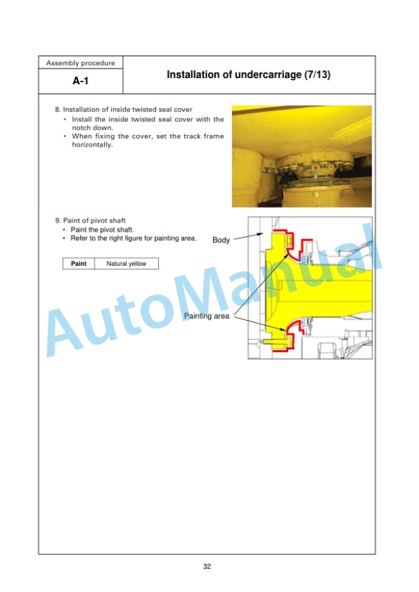
- 12.1. A1 Installation of undercarriage
- 12.2. A2 Installation of ripper
- 12.3. A3 Installation of tracks
- 12.4. A4 Adding oil to pivot chamber
- 12.5. A5 Installation of ripper shank
- 12.6. A6 Installation of blade lift cylinder
- 12.7. A7 Installation of trunnion
- 12.8. A8 Assembly of blade
- 12.9. A9 Adjustment of arm joint (Ublade)
- 12.10. A10 Installation of blade
- 12.11. A11 Installation of counterweight
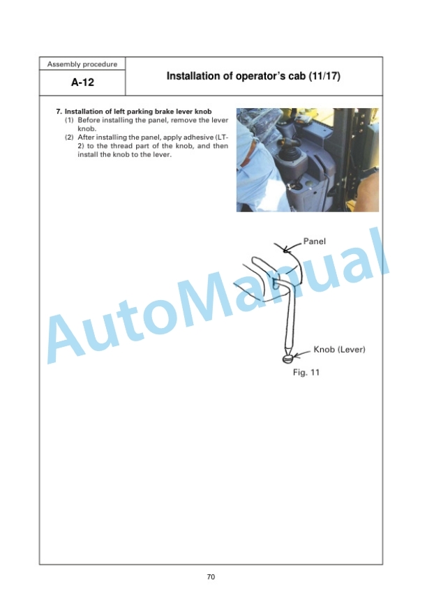
- 12.12. A12 Installation of operators cab
- 12.13. A13 Installation of ROPS
- 12.14. A14 Adjustment of potentiometer rod
- 12.15. A15 Procedure for adjusting blade tilt angle limit
- 12.16. A16 Method of checking autoreset system (Superdozer)
- 12.17. A17 Check track tension
- 12.18. A18 Checking oil/coolant levels
- 12.19. A19 Greasing of greasing point
- 12.20. A20 Installation of ORBCOMM antenna and wiring harness
- 12.21. A21 Replacement of return filter (Replacement of standard filter with flushing filter)
- 12.22. A22 Installing direction of exhaust pipe
- 12.23. A23 Bleeding air from hydraulic cylinders
- 12.24. A24 Installing lunchbox band (if equipped)
- 13. CHECK AND MAINTENANCE PROCEDURES AFTER COMPLETION OF ASSEMBLY
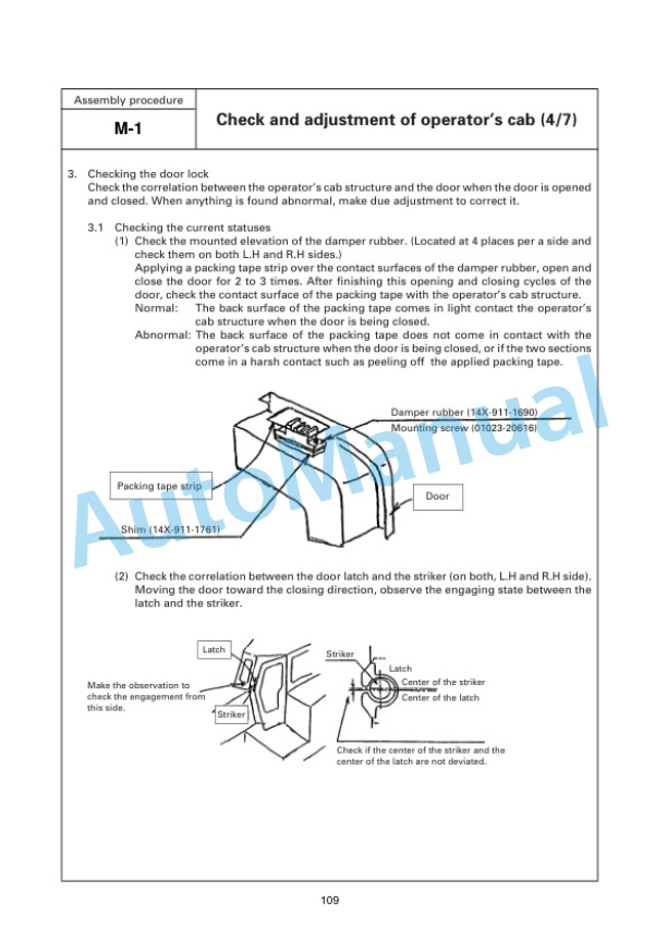
- 13.1. M1 Check and adjustment of operators cab
- 13.2. M2 Error code
- 13.3. M3 Flushing of hydraulic circuit
- 14. APPENDIX 1. INSTALLATION OF SPILL GUARDS
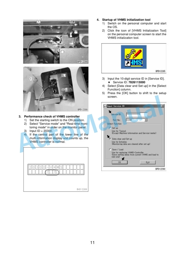
- 15. APPENDIX 2. PRECAUTIONS FOR INITIALIZATION PROCEDURES FOR VHMS CONTROLLER
- 16. FIELD ASSEMBLY INSPECTION REPORT (UDOZER SPECIFICATION)
- 17. FIELD ASSEMBLY INSPECTION REPORT (SUPERDOZER SPECIFICATION)


There are no reviews yet.