
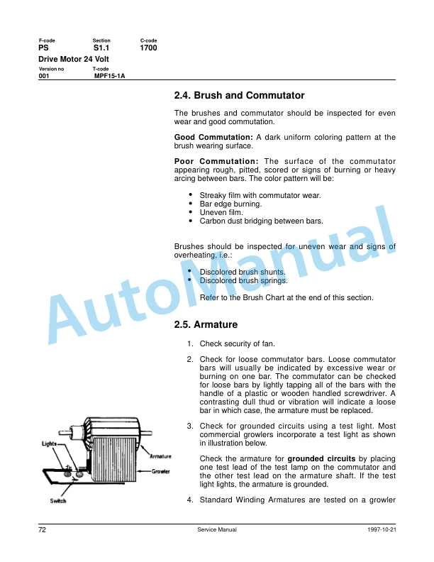
Description
-
Model List:
- MPF15-1A Forklift Truck
- 1. BVINTRO
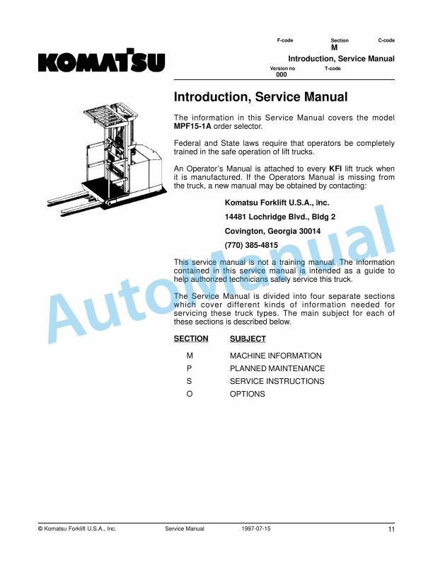
- 1.1. Introduction, Service Manual
- 1.2. Introduction, Service Manual
- 1.3. Contents, Section M
- 1.3.1. Machine Information
- 1.4. General Product Information
- 1.4.1. Presentation of the MPF151A
- 1.4.2. Main Components
- 1.5. Inch (SAE) and Metric Fasteners
- 1.5.1. Introduction
- 1.5.2. Nomenclature, Threads
- 1.5.3. Strength Identification
- 1.5.4. Conversion of Metric and English Units
- 2. BVELECT
- 2.1. Electrical System with TX and TT Card
- 2.1.1. Electrical Schematic Part 1
- 2.1.2. Electrical Schematic Part 2
- 2.1.3. Basics Of Circuit Operation
- 2.1.4. Control Features
- 2.1.5. General Maintenance Instructions
- 2.1.6. Troubleshooting Instructions
- 2.2. Battery Controller / Hourmeter / Lift Interrupt
- 2.2.1. General Information
- 2.2.2. Electrical
- 2.2.3. Battery Controller (BC)
- 2.2.4. Troubleshooting
- 2.3. Dash Display
- 2.3.1. General Information
- 2.3.2. Location
- 2.3.3. Operational Checks
- 2.3.4. Status Codes
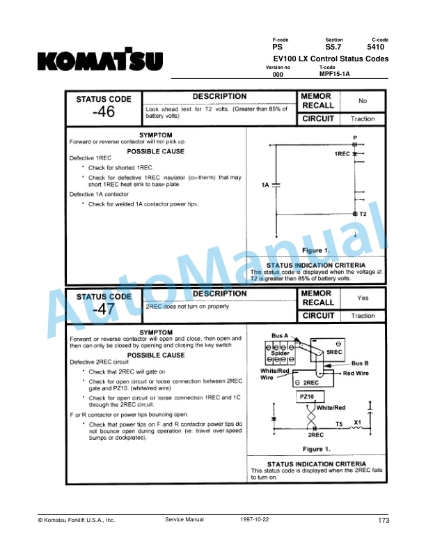
- 2.4. EV100 LX Control Status Codes
- 2.5. SCR Component Checks
- 2.5.1. Main Logic Card
- 2.5.2. Capacitor 1C
- 2.5.3. Contactors Forward, Rearward, 1A, Power Steering, and Pump
- 2.5.4. Potentiometer in Accelerator
- 2.5.5. SCRs (1REC, 2REC, 5REC)
- 2.5.6. Rectifiers (3REC, 4REC, Diode Blocks)
- 2.5.7. Thermal Protector (TP)
- 2.5.8. Filter Block (23FIL, etc.)
- 2.5.9. Filter Block (23FIL, etc.)
- 2.5.10. Choke and Reactor T3T4
- 2.5.11. Replacement of EV100 Components
- 2.5.12. Instructions EV100 Plugs
- 2.6. Direction Contactor
- 2.6.1. General Information
- 2.6.2. Remove / replace contact tips
- 2.7. Speed Contactor
- 2.7.1. General Information
- 2.7.2. Disassembly
- 2.7.3. Assembly
- 2.8. Electrical System Troubleshooting
- 2.8.1. Control Circuits and Power Circuits
- 2.9. Electrical System Troubleshooting Charts
- 2.10. Pump Contactor
- 2.10.1. General Information
- 2.10.2. Disassembly
- 2.10.3. Assembly
- 2.11. Steering Pump Contactor
- 2.11.1. General Information
- 2.11.2. Disassembly
- 2.11.3. Assembly
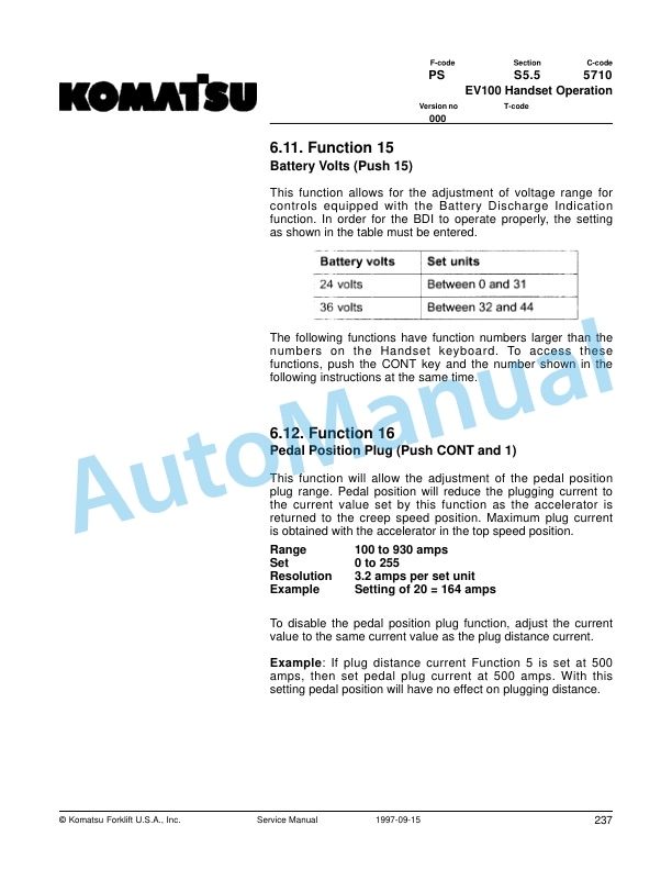
- 2.12. EV100 Handset Operation
- 2.12.1. General Information
- 2.12.2. Purpose
- 2.12.3. Operation
- 2.12.4. Function SetUp Procedures
- 2.12.5. Description and Location
- 2.12.6. Function Numbers for Controllers
- 3. BVHYDRA
- 3.1. Hydraulic System
- 3.1.1. Hydraulic Schematic
- 3.1.2. General Information
- 3.1.3. Maintenance
- 3.1.4. Adjustments
- 3.2. Hydraulic Troubleshooting
- 3.2.1. Troubleshooting Chart
- 3.3. Lift Pump Assembly
- 3.3.1. Shimming Mast on Truck.
- 3.3.2. Two Stage Mast
- 3.4. Mast, 3 Stage
- 3.4.1. Shimming Mast on Truck.
- 3.4.2. Three Stage Mast
- 3.5. Lift Cylinder, 2 Stage
- 3.5.1. Cylinder Repair
- 3.6. Freelift Cylinder, 3 Stage
- 3.6.1. Freelift Cylinder Repair
- 3.7. Staging Cylinder, 3 Stage
- 3.8. Micro 70 Wire Guidance Important Information
- 3.8.1. Powering Up
- 3.8.2. Powering Down
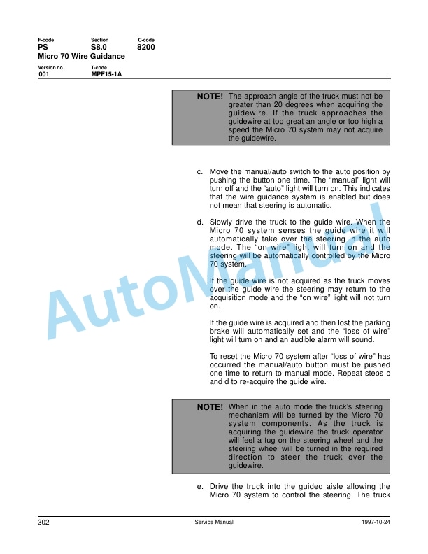
- 3.9. Micro 70 Wire Guidance
- 3.9.1. Electrical Schematic Part 1
- 3.9.2. Electrical Schematic Part 2
- 3.9.3. Electrical Schematic Part 3
- 3.9.4. Electrical Schematic Part 4
- 3.9.5. Cautions and Warnings
- 3.9.6. Operation Information
- 3.9.7. Component Function and Relationship
- 3.9.8. Truck Set Up On Site
- 3.9.9. Troubleshooting Information
- 3.9.10. Troubleshooting Charts
- 4. BVMAINT
- 4.1. Technical Service Data
- 4.2. Ordering Spare Parts
- 4.3. Introduction, Maintenance
- 4.3.1. Safe Jacking Procedure
- 4.4. Service Schedule
- 4.4.1. Planned Maintenance Schedule
- 4.5. Planned Maintenance Procedures
- 4.5.1. Services to be performed daily or at each 8 hour operating shift
- 4.5.2. Services to be performed monthly or every 250 operating hours
- 4.5.3. Services to be performed annually or every 1200 operating hours
- 4.6. Lubrication Chart
- 4.7. Oil and Grease Specifications
- 4.7.1. Approved Oils and Grease
- 4.8. Contents, Section S
- 4.8.1. Service Instructions
- 4.9. Inspection Covers
- 4.9.1. Removal Of Plastic Dash Panel
- 5. BVMOTORS
- 5.1. Drive Motor
- 5.1.1. General Information
- 5.1.2. Operating Conditions
- 5.1.3. Troubleshooting
- 5.2. Drive Motor 24 Volt
- 5.2.1. Component Repair
- 5.2.2. Inspection and Troubleshooting
- 5.2.3. When changing brushes
- 5.3. Drive Motor 36 Volt
- 5.3.1. Component Repair
- 5.3.2. Inspection and Troubleshooting
- 5.3.3. When Changing Brushes
- 5.4. Transmission
- 5.4.1. System description
- 5.4.2. Troubleshooting
- 5.4.3. Removal
- 5.5. Transmission Disassembly Assembly
- 5.5.1. Disassembly
- 5.5.2. Installation
- 6. BVSAFETY
- 6.1. Standard Codes
- 6.2. Warning Symbols
- 6.2.1. Warning Levels
- 6.3. Prohibitory Symbols
- 6.3.1. Ordinance Symbols
- 7. BVSTEER
- 7.1. Torque Generator
- 7.1.1. Disassembly
- 7.1.2. Assembly
- 7.2. Steering System Pump
- 7.2.1. General Information
- 7.3. Steering System
- 7.3.1. General Information
- 7.4. Stabilizing Caster Spring Loaded
- 7.4.1. Removal
- 7.4.2. Inspection
- 7.4.3. Disassembly


There are no reviews yet.