Komatsu MWL22-1A Forklift Truck Service Manual
$40.00
- Type Of Manual: Service Manual
- Format: PDF
- Size: 2.5MB
- Number of Pages: 243
Description
- 1. BXINTRO
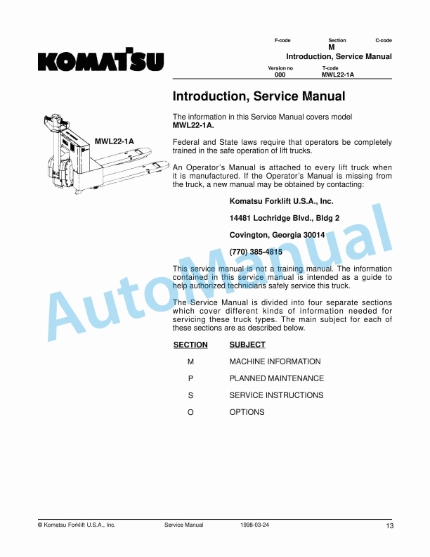
- 1.1. Introduction, Service Manual
- 1.2. Contents, Section M
- 1.2.1. Machine Information
- 1.3. General Product Information
- 1.3.1. Presentation of the MWL221A.
- 1.3.1.1. Intended Application of the Trucks
- 1.3.1.2. Forbidden Application of the Trucks
- 1.3.1.3. Truck Data
- 1.3.1.4. MWL221A Dimensions
- 1.3.1.5. Data Plate
- 1.3.2. Main Components
- 1.4. Inch (SAE) and Metric Fasteners
- 1.4.1. Introduction
- 1.4.2. Nomenclature, Threads
- 1.4.3. Strength Identification
- 1.4.4. Conversion of Metric and English Units
- 2. BXBATT
- 2.1. Swing Out Battery Pack
- 2.1.1. Charger Diagram
- 2.1.2. Battery Cable routing diagram
- 2.1.3. Troubleshooting
- 2.1.4. Electrical testing
- 2.2. GNB Battery Pack
- 2.2.1. General Information
- 2.2.2. Troubleshooting
- 2.2.2.1. Troubleshooting Symptom
- 2.3. Battery Controller / Hourmeter Lift Interrupt
- 2.3.1. General Information
- 2.3.2. Electrical
- 2.3.2.1. Voltage
- 2.3.3. Battery Controller (BC)
- 2.3.3.1. General Information
- 2.3.3.2. Reset
- 2.3.3.3. Key Switch
- 2.3.3.4. Hourmeter
- 2.3.4. Troubleshooting
- 2.3.4.1. Battery Discharge Indicator (BDI)
- 2.3.4.2. Hourmeter
- 2.4. Battery Discharge Indicator / Hourmeter
- 2.4.1. General Information
- 2.4.2. Electrical
- 2.4.2.1. Voltage
- 2.4.3. Battery Discharge Indicator (BDI)
- 2.4.3.1. General Information
- 2.4.3.2. Key Switch
- 2.4.3.3. Hourmeter
- 2.4.4. Troubleshooting
- 2.4.4.1. Battery Discharge Indicator (BDI)
- 2.4.4.2. Hourmeter
- 3. BXBRAKE
- 3.1. Parking Brake System
- 3.1.1. Brake Theory of Operation
- 3.1.2. Brake Adjustment
- 3.1.3. Brake Shoe Removal / Installation
- 3.2. Drive Wheel
- 3.2.1. Removal
- 3.2.2. Installation
- 3.3. Load Wheels
- 3.3.1. Removal/Installation
- 3.4. Steering
- 3.4.1. Control Handle Head
- 3.4.1.1. Removal
- 3.4.1.2. Installation
- 3.5. Steering Handle Head
- 3.5.1. Control Handle Head
- 3.5.1.1. Removal
- 3.5.1.2. Installation
- 3.5.2. Direction Control Switches
- 3.5.3. Horn, Raise, and Lower Switches
- 3.5.4. Potentiometer
- 4. BXELEC
- 4.1. MWL221A 12 Volt Electrical System
- 4.1.1. Electrical Panel Components
- 4.1.1.1. Electrical Schematic
- 4.1.1.2. Electrical Schematic Symbols
- 4.2. MWL221A 12 Volt Transistor Controller
- 4.2.1. Maintenance
- 4.2.1.1. Safety
- 4.2.1.2. Cleaning
- 4.2.1.3. Troubleshooting
- 4.2.2. Basics Of Circuit Operation
- 4.2.2.1. Battery connected and emergency disconnect switch in the RUN position.
- 4.2.2.2. Key switch turned ON
- 4.2.2.3. Control handle pulled down brakes released and brake interlock switch closed.
- 4.2.2.4. Reverse travel (fork direction) switch is closed.
- 4.2.2.5. Forward travel (control handle direction) switch is closed.
- 4.2.2.6. Curtis PMC controller power circuits.
- 4.2.2.7. Accelerator Potentiometer Circuits
- 4.2.2.8. Emergency Reverser Switch
- 4.2.2.9. Lift Pallet Forks
- 4.2.2.10. Lower Pallet Forks
- 4.2.2.11. Controller Adjustments
- 4.3. MWL221A 12 Volt Transistor Controller Troubleshooting
- 4.3.1. Troubleshooting Chart Index
- 4.3.2. Troubleshooting Charts
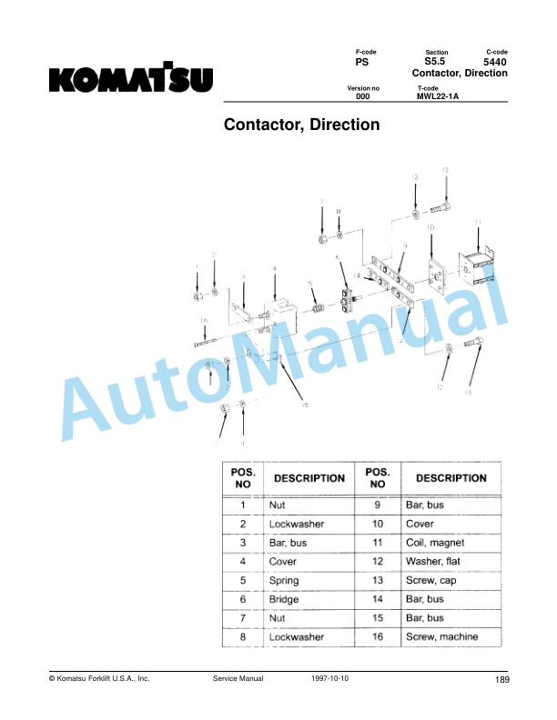
- 4.4. Contactor, Direction
- 4.4.1. Maintenance
- 4.4.1.1. Removal/Replacement of Contact Tips
- 4.5. MWL221A 24 Volt Electrical System
- 4.5.1. Electrical Panel Components
- 4.5.2. List of Symbols
- 4.5.2.1. Circuit Diagram 1(3)
- 4.5.2.2. Circuit Diagram 2(3)
- 4.5.2.3. Circuit Diagram 3(3)
- 4.5.3. Description of Function
- 4.5.3.1. General Information
- 4.5.3.2. References Information
- 4.5.3.3. Key Switch S17 in the ON Position
- 4.5.3.4. The Operating Arm in Drive Position, S10, Brake Switch Closed
- 4.5.3.5. Driving, Fork Direction
- 4.5.3.6. Driving, Steer Wheel Direction
- 4.5.3.7. Reversing/Motor Brake Fork Direction to Steer Wheel Direction
- 4.5.3.8. Reversing/Motor Brake Steer Wheel Direction to Fork Direction
- 4.5.3.9. Reverser switch
- 4.5.3.10. Lifting the Forks
- 4.5.3.11. Lowering the Forks
- 4.5.3.12. Horn
- 4.5.3.13. Lift lnterrupt
- 4.6. MWL221A 24 Volt, Transistor Controller
- 4.6.1. Maintenance
- 4.6.1.1. Safety
- 4.6.1.2. Cleaning
- 4.6.1.3. Diagnostics and Troubleshooting
- 4.6.2. Basics Of Circuit Operation
- 4.6.2.1. Control Feature
- 4.6.3. Motor Circuit
- 4.6.4. Control Circuit
- 4.6.5. Diagnostics and Troubleshooting
- 4.6.5.1. Programmer Diagnostics
- 4.6.5.2. Troubleshooting Chart
- 4.6.5.3. Technical Specification
- 4.6.5.4. Troubleshooting Chart Using the Handset
- 4.7. MWL221A 24 Volt, Transistor Controller Troubleshooting
- 4.7.1. Troubleshooting Chart Index
- 4.7.2. Troubleshooting Charts
- 4.8. Handset Operation
- 4.8.1. Operating Modes
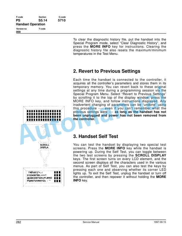
- 4.8.2. Revert to Previous Settings
- 4.8.3. Handset Self Test
- 5. BXHYDRA
- 5.1. Pump Motor
- 5.1.1. Component Repair
- 5.1.1.1. Motor Disassembly
- 5.1.2. Inspection and Troubleshooting
- 5.1.2.1. Drive End Head
- 5.1.2.2. Commutator End Head
- 5.1.2.3. Bearings
- 5.1.2.4. Brush and Commutator
- 5.1.2.5. Armature
- 5.1.2.6. Frame and Field Assembly
- 5.1.2.7. Assembly
- 5.1.3. Changing Brushes
- 5.2. Hydraulic System
- 5.2.1. Hydraulic Schematic
- 5.2.2. General Information
- 5.2.3. Description
- 5.2.3.1. Lift
- 5.2.3.2. Lower
- 5.2.3.3. Relief Pressure
- 5.2.4. Maintenance
- 5.2.5. Adjustments
- 5.2.6. Lift Limit Switch
- 5.2.7. Troubleshooting
- 5.3. Lift Pump Assembly
- 5.3.0.1. Solenoid Operated Valve
- 5.4. Lift Cylinder
- 5.4.1. Cylinder Repair
- 5.5. Technical Service Data
- 5.6. Ordering Spare Parts
- 5.7. Contents, Section P
- 5.7.1. Planned Maintenance
- 5.8. Introduction, Maintenance
- 5.8.1. Safe Jacking Procedure
- 5.9. Service Schedule
- 5.9.1. Planned Maintenance Schedule
- 5.9.2. Planned Maintenance Procedures
- 5.9.2.1. Services to be Performed Daily
- 5.9.2.2. Services to be Performed Monthly
- 5.9.2.3. Services to be Performed Annually
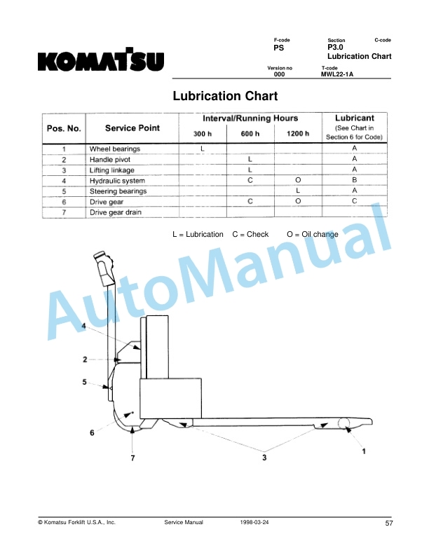
- 5.10. Lubrication Chart
- 5.11. Oil and Grease Specifications
- 5.11.1. Approved Oils and Grease
- 6. BXMOTOR
- 6.1. Drive Motor Mounting Points
- 6.1.1. Drive Motor Brush
- 6.1.1.1. Removal and Installation
- 6.1.2. Drive Motor Assembly
- 6.1.2.1. Remove
- 6.1.2.2. Installation
- 6.2. Drive Motor
- 6.2.1. General Information
- 6.2.2. Operating Conditions
- 6.2.3. Troubleshooting
- 6.3. Volt Drive Motor
- 6.3.1. Component Repair
- 6.3.1.1. Disassembly
- 6.3.2. Inspection and Troubleshooting
- 6.3.2.1. Drive End Head
- 6.3.2.2. Commutator End Head
- 6.3.2.3. Bearings
- 6.3.2.4. Brush and Commutator
- 6.3.2.5. Armature
- 6.3.2.6. Frame and Field Assembly
- 6.3.2.7. Assembly
- 6.3.3. Changing Brushes
- 6.4. Volt Drive Motor
- 6.4.1. Component Repair
- 6.4.1.1. Disassembly
- 6.4.2. Inspection and Troubleshooting
- 6.4.2.1. Drive End Head
- 6.4.2.2. Commutator End Head
- 6.4.2.3. Bearings
- 6.4.2.4. Brush and Commutator
- 6.4.2.5. Armature
- 6.4.2.6. Frame and Field Assembly
- 6.4.2.7. Assembly
- 6.4.3. Changing Brushes
- 6.5. Transmission
- 6.5.1. System Description
- 6.5.2. Troubleshooting
- 6.5.3. Axle Seal Removal and Installation
- 6.5.3.1. Removal
- 6.5.3.2. Installation
- 6.5.4. Transmission Removal/Installation
- 6.5.4.1. Removal
- 6.5.4.2. Installation
- 6.5.5. Transmission Assembly
- 6.5.5.1. Disassembly
- 6.5.5.2. Assembly
- 7. BXSAFETY
- 7.1. Standard Codes
- 7.2. Warning Symbols
- 7.2.1. Warning Levels
- 7.3. Prohibitory Symbols
- 7.3.1. Ordinance Symbols
- 8. BXSERV
- 8.1. Contents, Section S
- 8.1.1. Service Instructions
- 8.1.2. Carrier Frame Bushings
- 8.2. Chassis
- 8.2.1. General Information





There are no reviews yet.