

Description
-
Model List:
- PC650LC-11 Hydraulic Excavator
- 1. COVER
- 2. SPECIFICATIONS
- 3. PRECAUTIONS FOR FIELD ASSEMBLY
- 4. DISPOSAL OF REMOVED PARTS
- 5. ASSEMBLING PROCEDURES, APPLICABLE EQUIPMENT AND SCHEDULE
- 6. KIT LAYOUT DIAGRAM
- 7. FLOW OF FIELD ASSEMBLY
- 8. TRANSPORTATION
- 9. LIST OF TOOLS FOR FIELD ASSEMBLING
- 10. TIGHTENING TORQUE
- 11. COATING MATERIALS
- 12. SELECTION OF WIRE ROPES USED FOR ASSEMBLY
- 13. SELECTION OF NYLON SLINGS USED FOR ASSEMBLY
- 14. Assembly of Chassis
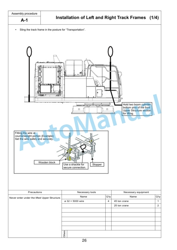
- 14.1. A1 Installation of Left and Right Track Frames
- 14.2. A2 Installation of Travel Pipe
- 14.3. A3 Installation of Operator Cabs Door Stopper and Striker
- 14.4. A4 Installation of Radiator Cover
- 14.5. A5 Installation of Rearview Mirror
- 14.6. A6 Installation of Handrail
- 14.7. A7 Installation of Step
- 14.8. A8 Installation of Left Side Step
- 14.9. A9 Sticking Sheet to Counterweight
- 14.10. A10 Installation of Rearview Camera
- 14.11. A11 Installation of Counterweight
- 14.12. A12 IInstallation of Step Light
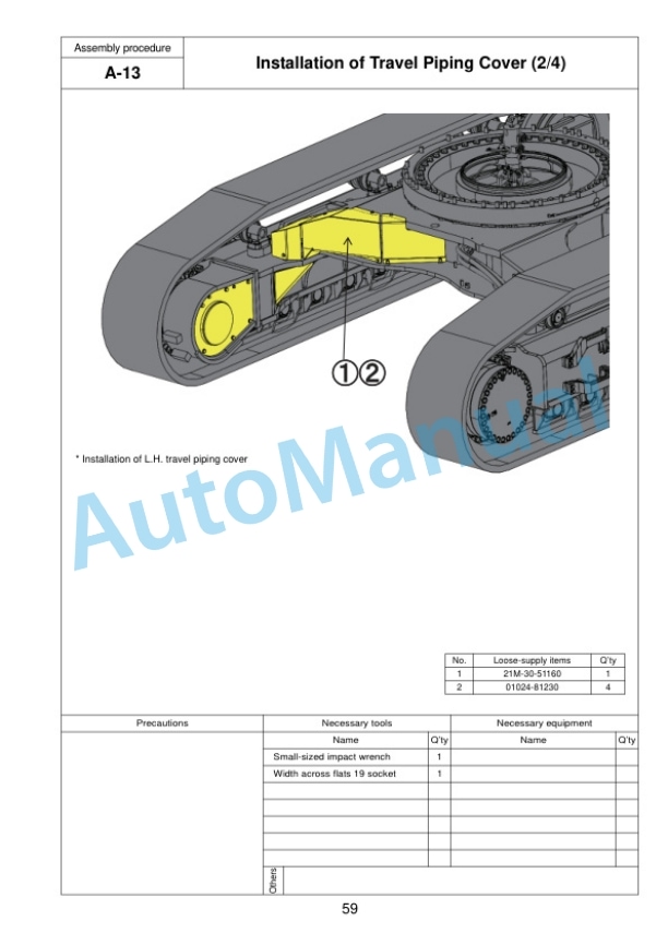
- 14.13. A13 Installation of Travel Piping Cover
- 14.14. A14 Testing Track Shoe Tension
- 15. Assembling of Work Equipment
- 15.1. B1 Assembly of Arm Cylinder
- 15.2. B2 Connection of Arm Cylinder Hoses
- 15.3. B3 Installation of Boom Cylinder
- 15.4. B4 Installation of Boom Cylinder Hoses
- 15.5. B5 Installation of Boom Foot Dust Seal
- 15.6. B6 Installation of Boom Assembly
- 15.7. B7 Installation of Hoses from Chassis Along Top of Boom
- 15.8. B8 Connection of Boom Cylinder Head
- 15.9. B9 Installation of Arm Assembly
- 15.10. B10 Installation of Bucket Cylinder Hoses between Boom and Bucket Cylinder
- 15.11. B11 Installation of Bucket
- 15.12. B12 Connection of Work Equipment Grease Piping
- 15.13. B13 Connection of Work Equipment Wiring
- 15.14. B14 Greasing after Assembling Work Equipment
- 15.15. B15 Bleeding Air from Work Equipment Circuit
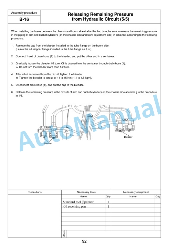
- 15.16. B16 Releasing Remaining Pressure from Hydraulic Circuit
- 16. Assembling of Counterweight Remover
- 16.1. D1 Sticking Sheet to Counterweight
- 16.2. D2 Adjustment of Shims for Counterweight
- 16.3. D3 Greasing
- 16.4. D4 Installation of Counterweight Remover
- 16.5. D5 Installation of Covers
- 16.6. D6 Installation of Clamps
- 16.7. D7 Installation of Hoses
- 16.8. D8 Bleeding Air from Counterweight Remover Circuit
- 16.9. D9 Installation of Counterweight
- 16.10. D10 Installation of Accessories
- 16.11. D11 Check of Operation
- 17. Procedure for Inspection and Maintenance after Completion of Assembly
- 17.1. M1 Replacement of Return Filter (Standard Filter to Flushing Filter)
- 17.2. M2 Flushing of Hydraulic Circuit
- 17.3. M3 Replacement of Return Filter (Flushing Filter to Standard Filter)
- 17.4. M4 Bleeding Air from Work Equipment Circuit
- 17.5. M5 Check of Oil/Coolant Level at Each Part
- 17.6. M6 Inspection of Oil Level in Hydraulic Tank and Refill
- 17.7. M7 Parts to be Touched up After Field Assembly
- 17.8. M8 Confirmation of Failure
- 18. Mounting bolt torque check sheet
- 19. Field Assembly Inspection Report (Backhoe)




There are no reviews yet.