
Description
-
Model List:
- WA600-8 Wheel Loader
- 1. Cover
- 2. Contents
- 3. Parts overview
- 4. Dimensions of main components
- 5. Layout of work space
- 6. Assembly general schedule
- 7. Facility, jig and consumable parts list
- 8. Oil, grease and paint
- 9. Assembly procedure
- 9.1. Oil, grease and coolant
- 9.2. Amount of oil, grease and coolant
- 9.3. Placing of bare machine (tireless specification)
- 9.4. Placing the front axle, rear axle, and bare machine
- 9.5. Installing the rear axle
- 9.6. Installing the front axle
- 9.7. Connecting the front axle through brake piping
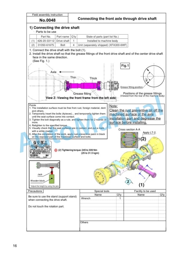
- 9.8. Connecting the front axle through drive shaft
- 9.9. Connecting the grease tube/connector
- 9.10. Connecting the brake tube piping
- 9.11. Connecting the rear axle through drive shaft
- 9.12. Installation of tire and rim assembly
- 9.13. Installation of radio antenna
- 9.14. Installation of KOMTRAX Plus antenna
- 9.15. Installation of ORBCOMM antenna
- 9.16. Removal of cab accessory
- 9.17. Installation of cab (1)
- 9.18. Removal of cab harness bracket
- 9.19. Installation of cab (2) (AJSS specification)
- 9.20. Installation of cab (2) (AJSS and steering wheel specification)
- 9.21. Installation of cab (3)
- 9.22. Installation of cab (4) (AJSS specification)
- 9.23. nstallation of cab (6) (AJSS and steering wheel specification)
- 9.24. Installation of cab harness (1)
- 9.25. Installing the CAB wiring harness (tilt steering wheel specification) (1)
- 9.26. Installation of cab harness (2)
- 9.27. Installation of cab harness (3)
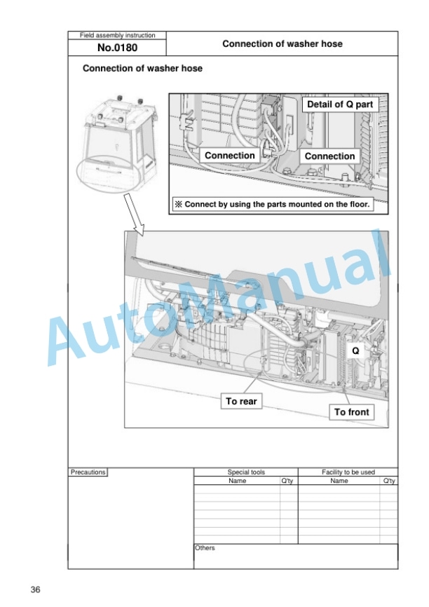
- 9.28. Connection of washer hose
- 9.29. Connection and fixing of KOMTRAX Plus harness
- 9.30. Installation of A/C duct
- 9.31. Installation of cab duct
- 9.32. Installing the air conditioner BOX
- 9.33. Installation of air conditioner box piping
- 9.34. Installation of filter
- 9.35. Installation of filter box cover
- 9.36. Installation of duct lower cover
- 9.37. Installation of duct cover
- 9.38. Installation of utility box
- 9.39. Installation of cab duct cover
- 9.40. Installation of relay cover
- 9.41. Fixing of ORBCOMM cable (ORBCOMM specification)
- 9.42. Installation of rear right side cover
- 9.43. Connection of cab ground
- 9.44. Installing the CAB front undercover
- 9.45. Installing the CAB rear undercover
- 9.46. Installation of stacked muffler
- 9.47. Installation of rear access ladder
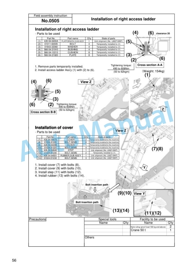
- 9.48. Installation of right access ladder
- 9.49. Installation of L.H. hand rail
- 9.50. Installation of R.H. hand rail
- 9.51. Adjustment of rearview mirror
- 9.52. Installing the additional working lamp (6XA04B LED additional wording lamp)
- 9.53. Installing the boom and bell crank assembly
- 9.54. Installing the boom positioner
- 9.55. Installing the bucket cylinder (bellcrank side)
- 9.56. Installing the front fender
- 9.57. Installing the front light support and connecting it
- 9.58. Installing the counterweight (standard specification)
- 9.59. Installing the counterweight (850kg specification)
- 9.60. Install pins (Standard specification)
- 9.61. Installing the L.H. platform handrail
- 9.62. Attaching the CAB decal (4XB01, 4XB997279 3V)
- 9.63. Check each part
- 9.64. Air bleeding of work equipment hydraulic circuit and each cylinders
- 9.65. Starting engine (1)
- 9.66. Air bleeding of brake
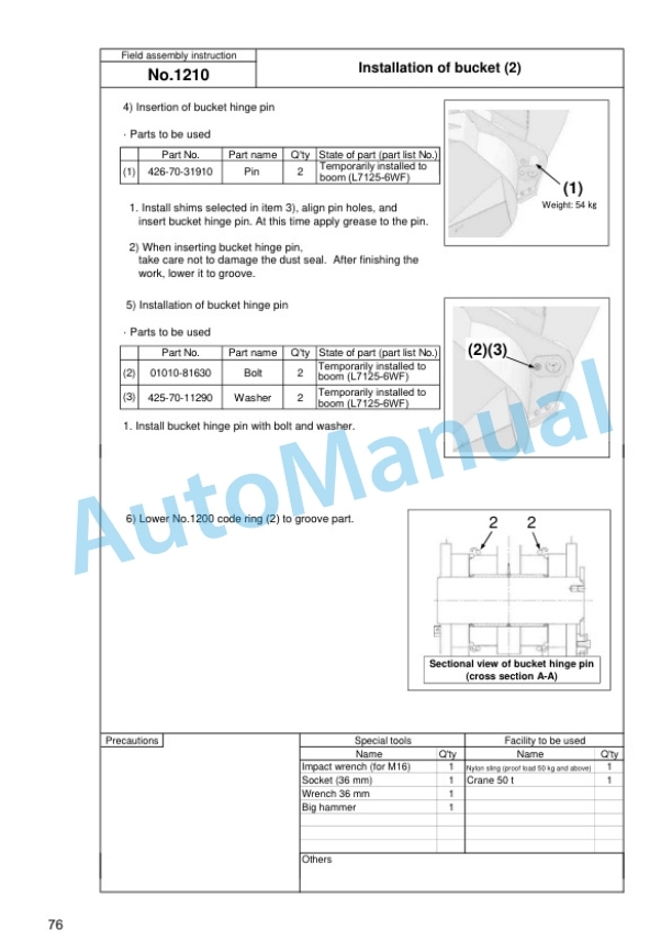
- 9.67. Installation of bucket (1)
- 9.68. Installation of bucket (2)
- 9.69. Installation of bucket (3)
- 9.70. Greasing (1st time)
- 9.71. Installation of floor mat (AJSS specification)
- 9.72. Greasing (2nd time)
- 9.73. Touch up work
- 9.74. Default Monitor panel and switch
- 9.75. Default Service menu
- 9.76. Default Optional device selection
- 9.77. Default Load meter unloaded adjustment
- 9.78. Initialize Adjust boom angle
- 9.79. Runningin
- 10. Appendix Machine check sheet for field assembly









There are no reviews yet.