
Description
-
Model List:
- WA800-3E0 Wheel Loader
- WA900-3E0 Wheel Loader
- 1. Cover
- 2. Dividing Process Overview (Major components alone)
- 3. Major Components Table of Dimensions
- 4. Work Space Layout
- 5. Schedule Table for Field Assembly
- 6. Facility, Jigs and Tools
- 7. List of Oil, Grease and Paints
- 8. Assembly procedure No.
- 8.1. Oil, grease and coolant
- 8.2. Oil, grease and coolant level
- 8.3. Setting rear frame in place
- 8.4. Setting front frame in place
- 8.5. Joining front and rear frames
- 8.6. Front and rear frames joining procedure
- 8.7. Assembling the steering pin (1/4)
- 8.8. Assembling the steering pin (2/4)
- 8.9. Assembling the steering pin (3/4)
- 8.10. Assembling the steering pin (4/4)
- 8.11. Assembling the center drive shaft (Center support Transmission)
- 8.12. Connection of piping (Part 1)
- 8.13. Connection of piping (Part 2)
- 8.14. Connection of piping (Part 2) (7XC47 Front and rear frame combination load figure)
- 8.15. Connection of piping (Part 2) (Riotinto specification If equipped)
- 8.16. Connecting the autogreasing pipe
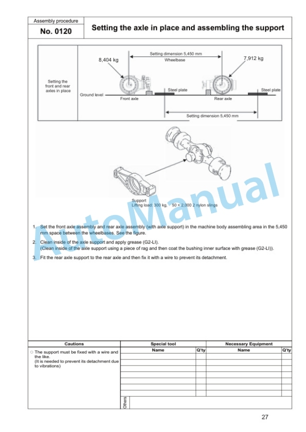
- 8.17. Setting the axle in place and assembling the support
- 8.18. Setting the bare machine in place
- 8.19. Assembling the rear axle
- 8.20. Rear axle rear side cover assembling procedure
- 8.21. Connecting the rear axle pipe
- 8.22. Fixing of rear axle piping (Brake cooling specification If equipped)
- 8.23. Connection of rear axle piping (Riotinto specification If equipped)
- 8.24. Fixing of rear axle piping (Brake cooling specification If equipped)
- 8.25. Connection of cooling line piping (Brake cooling specification If equipped)
- 8.26. Assembling the rear drive shaft (Transmission Rear axle)
- 8.27. Assembling the front axle
- 8.28. Fixing of front axle piping (Brake cooling specification If equipped)
- 8.29. Connection of front axle piping (Brake cooling specification If equipped)
- 8.30. Connecting the front axle pipe
- 8.31. Connection of front axle piping (Riotinto specification If equipped)
- 8.32. Connecting the front drive shaft (Front axle Center support)
- 8.33. Connection of front axle brake oil temperature sensor
- 8.34. Connecting the axle oil temperature sensor (For VHMS specification only)
- 8.35. Assembling the tires
- 8.36. Assembling the fuel tank
- 8.37. Installation of fuel tank (Riotinto specification If equipped)
- 8.38. Fixing the drain pipe
- 8.39. Fixing of torque converter cooler drain piping (Riotinto specification If equipped)
- 8.40. Connecting the fuel pipe
- 8.41. Fixing of breather hose
- 8.42. Fixing the engine drain hoses
- 8.43. Assembling the hydraulic tank ladder
- 8.44. Assembling the floor and cab assembly
- 8.45. Connecting the air conditioner hose
- 8.46. Connecting the brake line
- 8.47. Connecting the window washer hose
- 8.48. Connecting the PPC line hose
- 8.49. Connecting the floor wiring harness
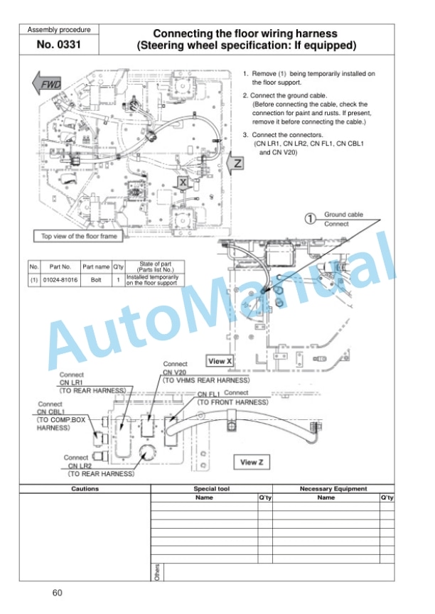
- 8.50. Connecting the floor wiring harness (Steering wheel specification If equipped)
- 8.51. Connection of floor wiring harness 1 (Riotinto specification If equipped)
- 8.52. Connection of floor wiring harness 2 (Riotinto specification If equipped)
- 8.53. Connecting the steering line (Steering wheel specification If equipped)
- 8.54. Connecting the link for AJSS (For AJSS specification only) 1
- 8.55. Connecting the link for AJSS (For AJSS specification only) 2
- 8.56. Connecting the link for AJSS (For AJSS specification only) 3
- 8.57. Connecting the link for AJSS (For AJSS specification only) 4
- 8.58. Calibration of the AJSS lever amgle and frame offset angle
- 8.59. Assembling the autogreasing pump and connecting the pipe (WA9003E0 North American specification)
- 8.60. Assembling the floor cover
- 8.61. Refilling the window washer
- 8.62. Assembling the battery box
- 8.63. Connecting and fixing the battery wiring
- 8.64. Wiring on right side of battery (Riotinto specification If equipped)
- 8.65. Wiring on left side of battery 1 (Riotinto specification If equipped)
- 8.66. Wiring on left side of battery 2 (Riotinto specification If equipped)
- 8.67. Wiring on left side of battery 3 (Riotinto specification If equipped)
- 8.68. Connection of ground cable on left side of battery (Riotinto specification If equipped)
- 8.69. Assembling the battery step
- 8.70. Installation of oil cooler assembly (Brake cooling specification If equipped)
- 8.71. Installation and connection of oil cooler assembly piping(Brake cooling specification If equipped)
- 8.72. Installation of oil cooler assembly piping 1 (Brake cooling specification If equipped)
- 8.73. Installation of oil cooler assembly piping 2 (Brake cooling specification If equipped)
- 8.74. Installation of handrail (R.H. platform)
- 8.75. Installation of handrail (Right platform area) (Brake cooling specification If equipped)
- 8.76. Assembling the handrail (On the hood top face)
- 8.77. Installation of handrail to step in front of CAB (PDI specification If equipped)
- 8.78. Installation of mirror to step in front of CAB (PDI specification If equipped)
- 8.79. Installation of handrail to upper surface of HOOD (PDI specification If equipped)
- 8.80. Installation of switch to upper surface of HOOD (PDI specification If equipped)
- 8.81. Installation of rear under view mirror (Rear under view mirror specification)
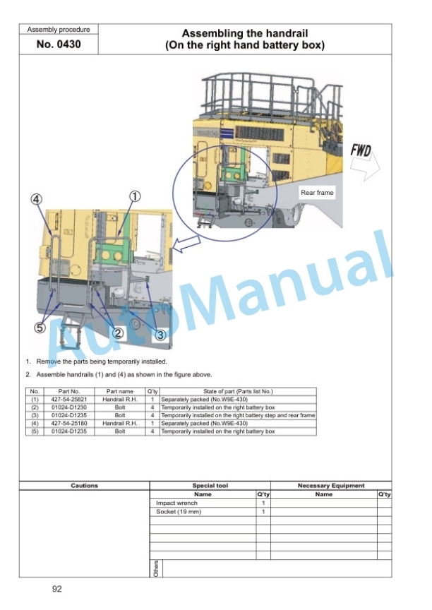
- 8.82. Assembling the handrail (On the right hand battery box)
- 8.83. Assembling the rear access step
- 8.84. Assembling the left handrail (Part 1)
- 8.85. Assembling the left handrail (Part 2)
- 8.86. Installation of left handrail (Part 2) (Brake cooling specification If equipped)
- 8.87. Assembling the rearview mirror
- 8.88. Installation of rearview mirrors (Brake cooling specification If equipped)
- 8.89. Assembling the exhaust pipe
- 8.90. Installation of oil cooler guard assembly (Brake cooling specification If equipped)
- 8.91. Installation of fan motor piping cover 1 (Brake cooling specification If equipped)
- 8.92. Installation of fan motor piping cover 2 (Brake cooling specification If equipped)
- 8.93. Applying the counterweight antislip
- 8.94. Assembling the counterweight (WA9003E0 standard specification)
- 8.95. Assembling the counterweight (WA9003E0 Highlift arm specification)
- 8.96. Assembling the counterweight (WA8003E0 Overseas general, optional specification and North American specification)
- 8.97. Assembling the counterweight (WA8003E0 Overseas general standard specification)
- 8.98. Assembling the front axle lamp and connecting the harness
- 8.99. Assembling the front lamp assembly
- 8.100. Assembling the ROPS canopy assembly
- 8.101. Assembling the tieoff bracket of ROPS
- 8.102. Assembling the yellow revolving lamp (yellow revolving lamp specification)
- 8.103. Assembling the antenna and work lamp
- 8.104. Assembling the VHMS antenna (For VHMS specification only)
- 8.105. Assembling the floor mat
- 8.106. Assembling the front fender
- 8.107. Engine starting procedure
- 8.108. Bleeding the brake air
- 8.109. Bleeding air from hydraulic circuit
- 8.110. Assembling the lift arm assembly (Part 1)
- 8.111. Assembling the lift arm assembly (Part 2)
- 8.112. Connecting the remote grease tube
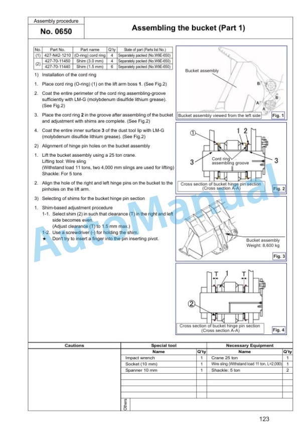
- 8.113. Assembling the bucket (Part 1)
- 8.114. Assembling the bucket (Part 2)
- 8.115. Assembling the bucket (Part 3)
- 8.116. Assembling the cover (Bottom of the counterweight)
- 8.117. Assembling the cover (Bottom of the counterweight)(For KAL PDI)
- 8.118. Feeding the grease
- 8.119. Work equipment hydraulic circuit air bleeding procedure
- 8.120. Adjusting the bucket positioner
- 8.121. Adjusting the new 2 stage (Overseas general standard)
- 8.122. Adjusting the new 2 stage (North American standard specification)
- 8.123. Assembling the lift arm angle sensor
- 8.124. Adjusting the active working system and boom kickout switch(Overseas general standard and domestic standard)
- 8.125. Touchup work
- 8.126. Applying the decal (For the overseasdirected products only)
- 8.127. Method for checking and inflating tire
- 9. Machine check sheet for field assembly



There are no reviews yet.