
Description
-
Model List:
- E25
- E40
- E45
- E50 Production site Aschaffenburg
- 1. Accumulator service case
- 1.1. Table of content
- 1.2. Introduction
- 1.2.1. General
- 1.3. Safety information
- 1.3.1. Symbols used
- 1.3.2. Safety information
- 1.4. Parts overview
- 1.4.1. Accumulator service case
- 1.4.2. Technical data
- 1.5. Operation
- 1.5.1. Checks before each use
- 1.5.2. Determining the filling pressure for accumulators for load damping in practice
- 1.5.3. Operating the accumulator service case
- 2. Pressin and pressout device for axle load sensors
- 2.1. Table of content
- 2.2. Safety information
- 2.2.1. Safety information for repair and maintenance work
- 2.3. Overview
- 2.3.1. Pressin and pressout device for axle load sensors
- 2.3.2. Basic device
- 2.3.2.1. Basic device
- 2.3.3. Seriesspecific changing parts
- 2.3.3.1. Seriesspecific changing parts
- 2.3.4. Column press
- 2.3.4.1. Technical data for the column press
- 2.4. Pressingin and pressingout process
- 2.4.1. Pressing out the sensor
- 2.4.2. Pressing in the sensor
- 2.5. Spare parts
- 2.5.1. Spare parts
- 3. Regular testing
- 3.1. Table of content
- 3.2. Regular testing
- 3.2.1. Principles for testing industrial trucks
- 3.2.2. Test log
- 3.2.3. Testing instruments, measuring devices, tools and devices
- 3.3. Electric motor
- 3.3.1. Test steps for the electric traction motor
- 3.4. Internal combustion engine
- 3.4.1. Test steps for the exhaust system
- 3.4.2. Diesel internal combustion engine
- 3.4.2.1. Exhaust gas test
- 3.4.2.2. Setpoint values for the exhaustgas check
- 3.4.3. LPG internal combustion engine
- 3.4.3.1. Exhaust gas test
- 3.5. Drive axle
- 3.5.1. Drive axle test steps
- 3.6. Chassis
- 3.6.1. Test steps for chassis
- 3.7. Drivers compartment
- 3.7.1. Test steps for drivers compartment
- 3.8. Steering systems
- 3.8.1. Test steps for the steering
- 3.9. Wheels and tyres
- 3.9.1. Test steps for wheels
- 3.9.2. Tyre test steps
- 3.10. Brake system
- 3.10.1. Definition and description of the industrial truck groups
- 3.10.2. Permissible braking distances for unladen industrial trucks
- 3.10.3. Service brake
- 3.10.4. Parking brake
- 3.11. Operating devices
- 3.11.1. Test steps for operating devices
- 3.12. Electrics.electronics
- 3.12.1. Test steps for electrical equipment
- 3.12.2. Notes regarding insulation testing
- 3.12.3. Insulation testing
- 3.12.4. Test steps for the battery and battery connection assemblies
- 3.13. Hydraulics
- 3.13.1. Test steps for hydraulic system
- 3.13.2. Safety regulations for hydraulic hose lines
- 3.14. Lift mast
- 3.14.1. Test steps for lift mast
- 3.14.2. Test steps for load chains
- 3.15. Load support
- 3.15.1. Test steps for fork arms
- 3.15.2. Combined testing device for testing fork arms, lifting chains and lifting hydraulics
- 3.16. Attachments
- 3.16.1. Test steps for attachments and other lifting accessories
- 3.17. Special equipment.accessories
- 3.17.1. LPG tanks on trucks
- 3.17.2. Test steps for other accessories
- 4. Service case Release tools for contacts
- 4.1. Table of content
- 4.2. Safety information
- 4.2.1. Safety information for repair and maintenance work
- 4.3. Information
- 4.3.1. Information
- 4.4. Overview
- 4.4.1. Overview of service cases
- 4.5. Plug systems
- 4.5.1. ATS 2.8 plug connector
- 4.5.2. CMC plug connector
- 4.5.3. DCS 9.5 plug connector
- 4.5.4. DIN 1.5mm circular connector
- 4.5.5. DIN 2.5mm circular connector
- 4.5.6. Deutsch DTM plug connector
- 4.5.7. ECU appliance plug
- 4.5.8. MCON appliance plug
- 4.5.9. Appliance plug with JPT and MQS contacts
- 4.5.10. Appliance plug with MT2 and JPT contacts
- 4.5.11. SICMA appliance plug
- 4.5.12. Econoseal JMark 2 plug connector
- 4.5.13. Elobau 11pin receptacle housing
- 4.5.14. E5931 plug connector
- 4.5.15. FASTINFASTON 6.3mm plug connector
- 4.5.16. GT150 plug connector
- 4.5.17. HDSCS plug connector
- 4.5.18. JPT plug connector
- 4.5.19. JPT SLD plug connector
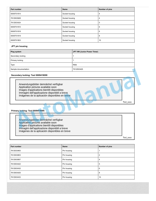
- 4.5.20. JPT plug connector Saab
- 4.5.21. JPT plug connector VW
- 4.5.22. Kompakt 1.1 plug connector
- 4.5.23. Bosch Kompakt 4 plug connector
- 4.5.24. Leavyseal plug connector
- 4.5.25. MCON 1.2mm LL plug connector
- 4.5.26. MCON 1.2mm CB plug connector
- 4.5.27. MCP plug connector
- 4.5.28. MetriPack 150 plug connector
- 4.5.29. MiniFit plug connector
- 4.5.30. Mini Universal MATENLOK plug connector
- 4.5.31. Mini relay socket for DFK 1.3 and MDK 1.3
- 4.5.32. MKR Plus plug connector
- 4.5.33. MQS plug connector
- 4.5.34. MR plug connector
- 4.5.35. MTA plug housing and fuse housing
- 4.5.36. MT2 plug connector
- 4.5.37. MT2 1.5mm plug connector VW
- 4.5.38. Multilock plug connector
- 4.5.39. MX150 plug connector
- 4.5.40. NG1 plug connector
- 4.5.41. Phönix Contact HC plug connector
- 4.5.42. PT 3F plug connector
- 4.5.43. Relay socket with SPT contacts for DFK 1.3.4 and MDK 1.3.4
- 4.5.44. Relay socket with SPT and MPT contacts
- 4.5.45. Fuse holder with SPT contacts
- 4.5.46. Sicma plug connector
- 4.5.47. SLK 2.8 plug connector
- 4.5.48. Souriau UTL7 plug connector
- 4.5.49. Superseal 1.5mm plug connector
- 4.5.50. Trident Neptune plug connector
- 4.5.51. Universal MATENLOK plug connector
- 4.5.52. VW 9.5mm plug connector
- 5. Electric truckE 35, E 40, E 45, E 50X 35, X 40, X 45, X 50
- 5.1. Table of content
- 5.2. Product information
- 5.2.1. Technical data
- 5.2.1.1. Type overview
- 5.2.2. Test specifications general
- 5.2.2.1. Checking that the system is deenergised
- 5.2.2.2. Insulation testing
- 5.2.2.3. Checking the screw fastenings
- 5.2.2.4. Screw failure classification A
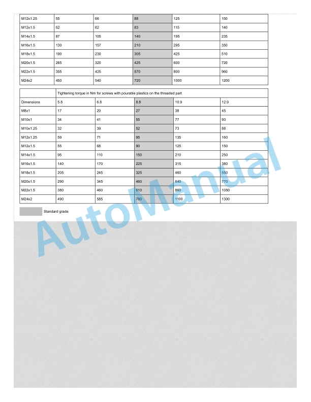
- 5.2.2.5. Standard tightening torques
- 5.2.2.6. Tightening torques according to units
- 5.2.3. Test specifications integrated charger
- 5.2.3.1. Requirements for qualified individuals
- 5.2.3.2. Testing the battery charger
- 5.2.3.3. Inspection procedure
- 5.2.3.4. Visual inspection
- 5.2.3.5. Measurement
- 5.2.3.6. Perform a functional test
- 5.2.3.7. Evaluation and documentation
- 5.2.4. Diagnostics
- 5.2.4.1. CAN box
- 5.2.4.2. USBCANBox 2 and BluetoothCANBox 3 software update
- 5.3. Service
- 5.3.1. Consumables
- 5.3.1.1. Lubricants and operating materials
- 5.3.1.2. Filling quantities, 1254 series
- 5.3.2. Servicing work
- 5.3.2.1. Service plan
- 5.3.2.2. Drive axle
- 5.3.2.3. Running gear and drive train
- 5.3.2.4. Chassis and bodywork
- 5.3.2.5. Drivers compartment
- 5.3.2.6. Electrics.electronics
- 5.3.2.7. Hydraulics
- 5.3.2.8. Lifting system
- 5.4. Running gear and drive train
- 5.4.1. Drive axle
- 5.4.1.1. Drive axle, E version
- 5.4.1.2. Drive axle, X version
- 5.4.1.3. Drive axle sensor
- 5.4.1.4. Axle mounting
- 5.4.2. Power modules
- 5.4.2.1. Drive axle power modules
- 5.4.2.2. KPC connections
- 5.4.2.3. Assembling the power module
- 5.4.3. Drive components
- 5.4.3.1. Wheel gear
- 5.4.4. Motor testing
- 5.4.4.1. Testing the AC motor
- 5.4.5. Brake system
- 5.4.5.1. Brake system function
- 5.4.5.2. Brake valve
- 5.4.5.3. Brake valve function table
- 5.4.5.4. Brake valve functions
- 5.4.5.5. Rinsing function for the brake valve
- 5.4.5.6. Towing the truck
- 5.4.5.7. Brake master cylinder


There are no reviews yet.