Yanmar 3TNV88C to 4TNV98CT Industrial Engine Service Manual
$30.00
- Type Of Manual: Service Manual
- Number of Pages: 326
- Size: 9.5MB
- Format: PDF
Description
-
Model List:
- 3TNV88C, 3TNV86CT, 3TNV86CHT, 3TN86CHT, 4TNV88C, 4TNV86CT, 4TNV86CHT, 4TN86CHT, 4TNV98C, 4TNV98CT
- 1. Table of Contents
- 2. Introduction
- 3. YANMAR Warranties
- 3.1. YANMAR Limited Warranty
- 3.1.1. What is Covered by this Warranty
- 3.1.2. How Long is the Warranty Period
- 3.1.3. What the Engine Owner must Do
- 3.1.4. To Locate an Authorized YANMAR Industrial Engine Dealer or Distributor
- 3.1.5. What YANMAR will Do
- 3.1.6. What is not Covered by this Warranty
- 3.1.7. Warranty Limitations
- 3.1.8. Warranty Modifications
- 3.1.9. Questions
- 3.2. Emission System Warranty
- 3.3. YANMAR POWER TECHNOLOGY CO., LTD. Limited Emission Control System Warranty
- 3.3.1. Your Warranty Rights and Obligations
- 3.3.2. Manufacturers Warranty Period
- 3.3.3. Warranty Coverage
- 3.3.4. Warranted Parts
- 3.3.5. Exclusions
- 3.3.6. Owners Warranty Responsibilities
- 3.3.7. What the Emergency Stationary Type Engine Owner must Do
- 3.4. Safety Statements
- 3.5. Safety Precautions
- 3.5.1. During Operation and Maintenance
- 4. General Service Information
- 4.1. Component Identification
- 4.1.1. NV88C, 3TNV86CT, 3TNV86CHT, 3TN86CHT, 4TNV88C, 4TNV86CT, 4TNV86CHT, 4TN86CHT
- 4.2. Location of Labels
- 4.2.1. Location of labels/nameplates on common rail system engine
- 4.2.2. Engine Nameplate (Typical)
- 4.3. Emission Control Regulations
- 4.3.1. EPA/ARB Regulations
- 4.4. Emission Control Labels
- 4.4.1. EPA/ARB labels (Typical)
- 4.4.2. The 97/68/EC Directive Certified Engines
- 4.5. Engine Family
- 4.6. Function of Major Engine Components
- 4.7. Function of Cooling System Components
- 4.8. Main Electronic Control Components and Features
- 4.9. Installation Position of Sensors
- 4.9.1. Cam Speed Sensor
- 4.9.2. New Air Temperature Sensor
- 4.9.3. EGR Temperature Sensor
- 4.9.4. Intake Temperature Sensor
- 4.9.5. Cooling Water Temperature Sensor
- 4.9.6. Exhaust Temperature Sensor
- 4.9.7. Diesel Particulate Filter (DPF) Inside/Inlet Temperature Sensor
- 4.9.8. Rail Pressure Sensor
- 4.9.9. EGR Pressure Sensor (Excluding 3TN86CHT and 4TN86CHT Engines)
- 4.9.10. Intake Pressure Sensor (3TN86CHT, 4TN86CHT)
- 4.9.11. Exhaust Pressure Sensor (3TN86CHT, 4TN86CHT)
- 4.9.12. EGR Valve
- 4.9.13. Intake Air Throttles
- 4.9.14. Exhaust Air Throttles
- 4.10. Diesel Fuel
- 4.10.1. Diesel Fuel Specifications
- 4.10.2. Filling The Fuel Tank
- 4.10.3. Priming the Fuel System
- 4.11. Engine Lubricating Oil
- 4.11.1. Engine Lubricating Oil Specifications
- 4.11.2. Engine Lubricating Oil Viscosity
- 4.11.3. Checking Engine Lubricating Oil
- 4.11.4. Adding Engine Lubricating Oil
- 4.11.5. Engine Oil Capacity (Typical)
- 4.12. Engine Coolant
- 4.12.1. Engine Coolant Specifications
- 4.12.2. Filling Radiator with Engine Coolant
- 4.12.3. Daily Check of the Cooling System
- 4.12.4. Engine Coolant Capacity (Typical)
- 4.13. Specifications
- 4.13.1. Description of Model Number
- 4.13.2. Engine General Specifications
- 4.14. Principal Engine Specifications
- 4.14.1. NV88C
- 4.15. Engine Service Standards
- 4.16. Tightening Torques for Standard Bolts and Nuts
- 4.17. Abbreviations and Symbols
- 4.17.1. Abbreviations
- 4.17.2. Symbols
- 4.18. Unit Conversions
- 4.18.1. Unit prefixes
- 4.18.2. Units of length
- 4.18.3. Units of volume
- 4.18.4. Units of mass
- 4.18.5. Units of force
- 4.18.6. Units of torque
- 4.18.7. Units of pressure
- 4.18.8. Units of power
- 4.18.9. Units of temperature
- 5. Periodic Maintenance
- 5.1. Before You Begin Servicing
- 5.2. Introduction
- 5.2.1. The Importance of Periodic Maintenance
- 5.2.2. Performing Periodic Maintenance
- 5.2.3. YANMAR Replacement Parts
- 5.2.4. Required EPA/ARB Maintenance
- 5.2.5. EPA/ARB Installation Requirements
- 5.3. Periodic Maintenance Schedule
- 5.4. Periodic Maintenance Procedures
- 5.4.1. After Initial 50 Hours of Operation
- 5.4.2. Every 50 Hours of Operation
- 5.4.3. Every 250 Hours of Operation
- 5.4.4. Every 500 Hours of Operation
- 5.4.5. Every 1000 Hours of Operation
- 5.4.6. Every 1500 Hours of Operation
- 5.4.7. Every 2000 Hours of Operation
- 5.4.8. Every 3000 Hours of Operation
- 5.4.9. On 6000 Hours of Operation and After 6000 Hours of Replacement
- 5.4.10. Replace Every 9000 Hours
- 5.5. Before You Begin Servicing
- 5.6. INTRODUCTION
- 5.7. Cylinder Head Specifications
- 5.7.1. Adjustment Specifications
- 5.7.2. Cylinder Head
- 5.7.3. Rocker Arm and Shaft
- 5.7.4. Valve Spring
- 5.8. Camshaft and Timing Gear Train Specifications
- 5.8.1. Camshaft
- 5.8.2. Timing Gear Backlash
- 5.9. Crankshaft and Piston Specifications
- 5.9.1. Crankshaft
- 5.10. Cylinder Block Specifications
- 5.10.1. Cylinder Block
- 5.11. Special Torque Chart
- 5.11.1. Torque for Bolts and Nuts
- 5.12. Special Service Tools
- 5.13. Measuring Instruments
- 5.14. Cylinder Head
- 5.14.1. Cylinder Head Components
- 5.14.2. Disassembly of Cylinder Head
- 5.14.3. Removing the Glow Plugs
- 5.14.4. Removal of Cylinder Head Cover
- 5.14.5. Removal of Rocker Arm Assembly
- 5.14.6. Disassembly of Rocker Arm Assembly
- 5.14.7. Removal of Cylinder Head
- 5.14.8. Removal of Intake/exhaust Valves
- 5.14.9. Removal of Valve Guides
- 5.14.10. Cleaning of Cylinder Head Components
- 5.14.11. Inspection of Cylinder Head Components
- 5.14.12. Inspection of Push Rods
- 5.14.13. Inspection of Rocker Arm Assembly
- 5.14.14. Inspection of Valve Guides
- 5.14.15. Inspection of Cylinder Head
- 5.14.16. Inspection of Intake and Exhaust Valves
- 5.14.17. Inspection of Valve Springs
- 5.14.18. Reassembly of Cylinder Head
- 5.15. Measuring and Adjusting Valve Clearance
- 5.15.1. cylinder engines
- 5.15.2. cylinder engines
- 5.16. Crankshaft and Camshaft Components
- 5.16.1. Disassembly of Engine
- 5.16.2. Disassembly of Camshaft and Timing Components
- 5.16.3. Disassembly of Crankshaft and Piston Components
- 5.16.4. Inspection of Crankshaft and Camshaft Components
- 5.16.5. Honing and Boring
- 5.16.6. Reassembly of Crankshaft and Piston Components
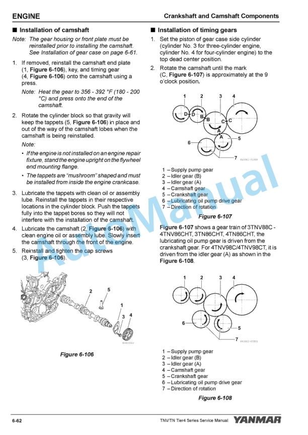
- 5.16.7. Reassembly of Camshaft and Timing Components
- 5.16.8. Final Reassembly of Engine
- 5.17. EGR System
- 5.17.1. EGR System Configuration
- 5.17.2. Disassembly of EGR System
- 5.17.3. Cleaning the EGR Cooler (Water Side/Exhaust Passage Blower)
- 5.17.4. Cleaning the EGR Pipe and Other Connecting Elbows
- 5.17.5. Check, Clean, and Test EGR Valve
- 5.17.6. Cleaning the EGR Lead Valves
- 5.17.7. Assembling around the EGR Valve
- 5.18. Intake Throttle
- 5.18.1. Precautions for Handling the Intake Throttle
- 5.19. Exhaust Throttle
- 5.19.1. Checking the Operation of Exhaust Throttle
- 6. Fuel System
- 6.1. Before You Begin Servicing
- 6.2. System Structure
- 6.2.1. Supply pump
- 6.2.2. Injector
- 6.3. Fuel System Specifications
- 6.3.1. Torque Chart for Major Bolts and Nuts
- 6.4. Fuel System Diagram
- 6.5. Fuel System Components
- 6.5.1. Removal of Injector
- 6.5.2. Reassembly of injector
- 6.5.3. Removal of Common Rail
- 6.5.4. Reassembly of Common Rail
- 6.5.5. Removal of Supply Pump
- 6.5.6. Reassembly of Supply Pump
- 7. Cooling System
- 7.1. Before You Begin Servicing
- 7.2. INTRODUCTION
- 7.3. Cooling System Diagram
- 7.4. Engine Coolant Pump Components
- 7.5. Engine Coolant System Check
- 7.6. Engine Coolant Pump
- 7.6.1. Removal of Engine Coolant Pump
- 7.6.2. Disassembly of Engine Coolant Pump
- 7.6.3. Cleaning and Inspection
- 7.6.4. Reassembly of Engine Coolant Pump
- 7.6.5. Installation of Engine Coolant Pump
- 8. Lubrication System
- 8.1. Before You Begin Servicing
- 8.2. Introduction
- 8.3. Oil Pump Service Information
- 8.3.1. Engine lubricating oil pressure
- 8.3.2. Outer rotor outside clearance
- 8.3.3. Outer rotor side clearance
- 8.3.4. Rotor shaft clearance
- 8.4. Lubrication System Diagram
- 8.5. Checking Engine Lubricating Oil Pressure
- 8.6. Oil Pump Components
- 8.6.1. NV88C, 3TNV86CT, 3TNV86CHT, 3TN86CHT, 4TNV88C, 4TNV86CT, 4TNV86CHT, 4TN86CHT
- 8.6.2. Disassembly of Oil Pump
- 8.6.3. Cleaning and Inspection
- 8.6.4. Reassembly of Oil Pump
- 8.6.5. NV98C, 4TNV98CT (Trochoid Oil Pump)
- 8.6.6. Disassembly of Oil Pump
- 8.6.7. Cleaning and Inspection
- 8.6.8. Reassembly of Oil Pump
- 9. Turbocharger
- 9.1. Before You Begin Servicing
- 9.2. Introduction
- 9.3. Specifications
- 9.3.1. Turbocharger Service Information
- 9.4. Troubleshooting
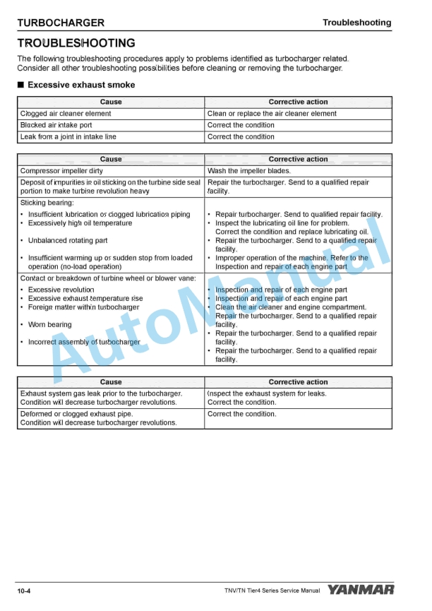
- 9.4.1. Excessive exhaust smoke
- 9.4.2. Sudden oil decrease
- 9.4.3. Decrease in output
- 9.4.4. Poor (slow) response (starting) of turbocharger
- 9.4.5. Abnormal sound or vibration
- 9.5. Turbocharger Components
- 9.6. Turbocharger Component Functions
- 9.6.1. Structure of Turbocharger
- 9.6.2. Role of Waste Gate
- 9.7. Periodic Inspection
- 9.7.1. Visual Inspection
- 9.7.2. Inspection of Rotor Rotation
- 9.7.3. Checking Rotor Play
- 9.7.4. Waste Gate Valve Test
- 9.7.5. Waste Gate Actuator Leak Test
- 9.8. Removal and Installation of Turbocharger
- 9.8.1. Removal of Turbocharger
- 9.8.2. Installation of Turbocharger
- 9.9. Cleaning Procedure
- 10. Starter Motor
- 10.1. Before You Begin Servicing
- 10.2. INTRODUCTION
- 10.3. Starter Motor Information
- 10.3.1. NV88C to 4TNV86CHT, 3TN86CHT, 4TN86CHT – Standard and Optional
- 10.3.2. NV98C and 4TNV98CT – Standard and Optional
- 10.4. Starter Motor Specifications
- 10.5. Starter Motor Troubleshooting
- 10.6. Starter Motor Components
- 10.7. Starter Motor
- 10.7.1. Removal of Starter Motor
- 10.7.2. Disassembly of Starter Motor
- 10.7.3. Cleaning and Inspection
- 10.7.4. Reassembly of Starter Motor
- 10.7.5. Check Pinion Projection Length
- 10.7.6. No-Load Test
- 10.7.7. Installation of Starter Motor
- 11. Alternator
- 11.1. Before You Begin Servicing
- 11.2. Introduction
- 11.3. Dynamo and Alternator Information
- 11.3.1. NV88C to 4TNV98CT, 3/4TN86CHT – Standard and Optional Dynamos
- 11.3.2. NV88C to 4TNV98CT, 3/4TN86CHT – Standard and Optional Alternators
- 11.4. Alternator Specifications
- 11.5. Dynamo Specifications
- 11.6. Alternator Troubleshooting
- 11.7. Alternator Components
- 11.8. Alternator Wiring Diagram
- 11.9. Alternator Standard Output
- 11.10. Alternator
- 11.10.1. Removal of Alternator
- 11.10.2. Disassembly of Alternator
- 11.10.3. Reassembly of Alternator
- 11.10.4. Installation of Alternator
- 11.11. Dynamo Component Location
- 11.12. Dynamo Wiring Diagram
- 11.13. Operation of Dynamo
- 11.14. Dynamo Standard Output
- 11.15. Testing of Dynamo
- 11.15.1. Testing Stator Coil Continuity
- 11.15.2. Testing Stator Coil Short-to-Ground
- 11.15.3. Testing Dynamo Regulated Output
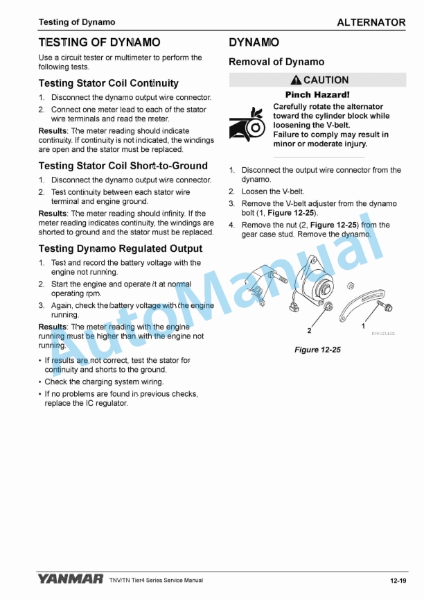
- 11.15.4. Removal of Dynamo
- 11.15.5. Disassembly of Dynamo
- 11.15.6. Reassembly of Dynamo
- 11.15.7. Installation of Dynamo
- 12. Electronic Control System
- 12.1. Before You Begin Servicing
- 12.2. Introduction
- 12.3. System Structure
- 12.3.1. Diesel Particulate Filter (DPF)
- 12.4. HOW TO REMOVE AND REATTACH THE DIESEL PARTICULATE FILTER (DPF)
- 12.4.1. How to remove the soot filter (SF) case
- 12.4.2. How to reattach the SF case
- 12.4.3. How to remove the DPF unit
- 12.4.4. How to reattach the DPF
- 12.5. SF and DPF Maintenance Kit
- 12.6. Troubleshooting of Electronic Control System
- 12.6.1. Fault Detection Capability
- 12.6.2. SMARTASSIST-DIRECT (SA-D)
- 12.7. Replacement of Components
- 12.7.1. Processing the DPF regeneration after the parts replacement
- 12.7.2. Processing after the ECU replacement (when it is impossible to inherit from the old ECU)
- 12.7.3. Required processing at the CR-related parts replacement
- 12.8. Electronic Control Harness Connections
- 12.8.1. Wiring Diagram
- 12.8.2. List of Terminal
- 12.8.3. Coupler Diagram
- 13. Electric Wiring
- 13.1. Electric Wiring Precautions
- 13.2. Electrical Wire Resistance
- 13.3. Battery Cable Resistance
- 13.4. Electrical Wire Sizes – Voltage Drop
- 13.5. Conversion of AWG to European Standards
- 14. Failure Diagnosis
- 14.1. Special Service Tools
- 14.2. Troubleshooting by Measuring Compression Pressure
- 14.2.1. Compression Pressure Inspection Procedures
- 14.2.2. Attaching the Injector
- 14.2.3. Engine Speed and Compression Pressure (Use for Reference)
- 14.3. Measured Value and Troubleshooting
- 14.4. Quick Reference Table for Troubleshooting



,%202GM20(F)(C),%203GM30(F)(C),%203HM35(F)(C)%20Engine%20Service%20Manual&url=https://pdfrepairmanual.com/docs/yanmar-1gm10c-2gm20fc-3gm30fc-3hm35fc-engine-service-manual/&media=https://pdfrepairmanual.com/wp-content/uploads/2026/01/yanmar-1gm10c-2gm20fc-3gm30fc-3hm35fc-engine-service-manual-1.jpg)

,%202GM20(F)(C),%203GM30(F)(C),%203HM35(F)(C)%20Marine%20Diesel%20Engine%20Service%20Manual&url=https://pdfrepairmanual.com/docs/yanmar-1gm10c-2gm20fc-3gm30fc-3hm35fc-marine-diesel-engine-service-manual/&media=https://pdfrepairmanual.com/wp-content/uploads/2026/01/yanmar-1gm10c-2gm20fc-3gm30fc-3hm35fc-marine-diesel-engine-service-manual-1.jpg)


There are no reviews yet.