

Description
-
Model List:
- V65 Wheel Loader
- 1. V65 – Cover – TL0065_1063 XXXX
- 1.1. List of Contents
- 1.2. General
- 1.2.1. Introduction / user notice
- 1.2.2. Safety and accident prevention
- 1.2.3. Symbol and hazard descriptions
- 1.2.4. Tightening torques for pistons or piston nuts
- 1.2.5. Tightening torques for guide bushings
- 1.2.6. Pictograms
- 1.2.7. Measuring connections
- 1.2.8. Units and conversion tables
- 1.3. Technical Data
- 1.3.1. Technische Daten
- 1.3.2. Drift values
- 1.4. Diesel Engine
- 1.4.1. Operation manual DEUTZ D/TD/TCD2011
- 1.4.1.1. Foreword
- 1.4.1.2. Contents
- 1.4.1.3. General
- 1.4.1.4. Engine description
- 1.4.1.4.1. Engine Illustrations
- 1.4.1.4.2. Lubricating oil schematic
- 1.4.1.4.3. Fuel schematic
- 1.4.1.4.4. Coolant schematic
- 1.4.1.4.5. Exhaust gas recirculation
- 1.4.1.4.6. Electrics/Electronics
- 1.4.1.5. Operation
- 1.4.1.5.1. Ambient conditions
- 1.4.1.5.2. Initial commissioning
- 1.4.1.5.3. Start procedure
- 1.4.1.5.4. Operation monitoring
- 1.4.1.5.5. Stop procedure
- 1.4.1.6. Operating media
- 1.4.1.6.1. Lubricating oil
- 1.4.1.6.2. Coolant
- 1.4.1.7. Maintenance
- 1.4.1.7.1. Maintenance schedule
- 1.4.1.8. Care and maintenance work
- 1.4.1.8.1. Lubricating oil system
- 1.4.1.8.2. Fuel system
- 1.4.1.8.3. Cooling system
- 1.4.1.8.4. Engine cleaning
- 1.4.1.8.5. Suction system
- 1.4.1.8.6. Belt drives
- 1.4.1.8.7. Electrical system
- 1.4.1.8.8. Fault table
- 1.4.1.8.9. Engine management
- 1.4.1.9. Transport and storage
- 1.4.1.9.1. Transport
- 1.4.1.9.2. Protecting the engine against corrosion
- 1.4.1.10. Technical data
- 1.4.1.10.1. Engine and setting data
- 1.4.2. Workshop manual DEUTZ D/TD/TCD 2011
- 1.4.2.1. Table of contents
- 1.4.2.1.1. Foreword
- 1.4.2.1.2. General
- 1.4.2.1.3. User notes
- 1.4.2.1.4. Technical data
- 1.4.2.1.5. Job card overview
- 1.4.2.1.6. Job cards
- 1.4.2.2. Checking the compression pressure
- 1.4.2.3. Mounting engine on assembly block and demounting
- 1.4.2.4. Setting valve clearance
- 1.4.2.5. Removing and installing the rocker arm and rocker arm bracket
- 1.4.2.6. Disassembling, assembling and checking the rocker arm and rocker arm bracket
- 1.4.2.7. Removing and installing cylinder head
- 1.4.2.8. Checking piston overhang
- 1.4.2.9. Removing and installing the crankcase bleeding
- 1.4.2.10. Removing and installing the exhaust line
- 1.4.2.11. Removing and install the charge air line
- 1.4.2.12. Removing and installing the turbocharger
- 1.4.2.13. Removing and installing the intake manifold
- 1.4.2.14. Removing and installing the exhaust gas return valve
- 1.4.2.15. Removing and installing the exhaust gas return pipe
- 1.4.2.16. Removing and installing the exhaust gas collection pipe (Exhaust gas recirculationl
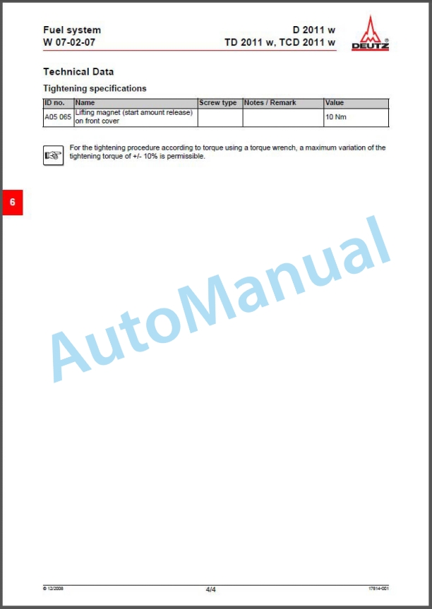
- 1.4.2.17. Removing and installing the lifting magnet (Start amount release)
- 1.4.2.18. Renewing the injection lines
- 1.4.2.19. Removing and installing the fuelinjectors
- 1.4.2.20. Removing and installing the lifting magnet (charge air pressure-dependent full load stop)
- 1.4.2.21. Installing and removing charge air pressure-dependent full load stop
- 1.4.2.22. Removing and installing fuel pipes
- 1.4.2.23. Removing and installing the fuel filter console
- 1.4.2.24. Removing and installing the fuel supply pump
- 1.4.2.25. Removing and installing the lubricating oil cooler
- 1.4.2.26. Removing and installing the oil filter console
- 1.4.2.27. Removing and installing the oil pressure switch
- 1.4.2.28. Removing and installing the thermostat (Lubricating oil cooler)
- 1.4.2.29. Removing and installing the control line
- 1.4.2.30. Removing and installing the coolant pump
- 1.4.2.31. Checking the thermostat (in the removed state)
- 1.4.2.32. Removing and installing the thermostat
- 1.4.2.33. Removing and installing the thermostat housing
- 1.4.2.34. Removing and installing temperature transmitter
- 1.4.2.35. Removing and installing the lifting magnet (Engine shutdown)
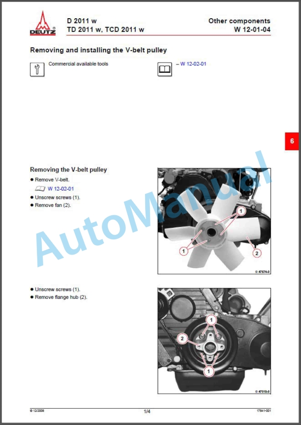
- 1.4.2.36. Removing and installing the V-belt pulley
- 1.4.2.37. Renew V-belts, check V-belt tension
- 1.4.2.38. Removing and installing the flywheel
- 1.4.2.39. Removing and installing the hydraulic pump
- 1.4.2.40. Removing and installing the generator
- 1.4.2.41. Removing and installing the starter
- 1.4.2.42. Removing and installing the heating plugs
- 1.4.2.43. Removing and installing the glow plug
- 1.4.2.44. Standard tools
- 1.4.2.45. Special tools
- 1.5. Hydraulics
- 1.5.1. Hydraulic circuit diagram Parallel-Kinematic Standard
- 1.5.2. Hydraulic circuit diagramZ-Kinematic Standard
- 1.5.3. Hydraulic circuit diagram Parallel-Kinematic Additional circuit and options
- 1.5.4. Hydraulic circuit diagram Z-Kinematic Additional circuit and options
- 1.6. Setting Instructions
- 1.6.1. General setting instructions
- 1.6.2. Hydromatik tightening values
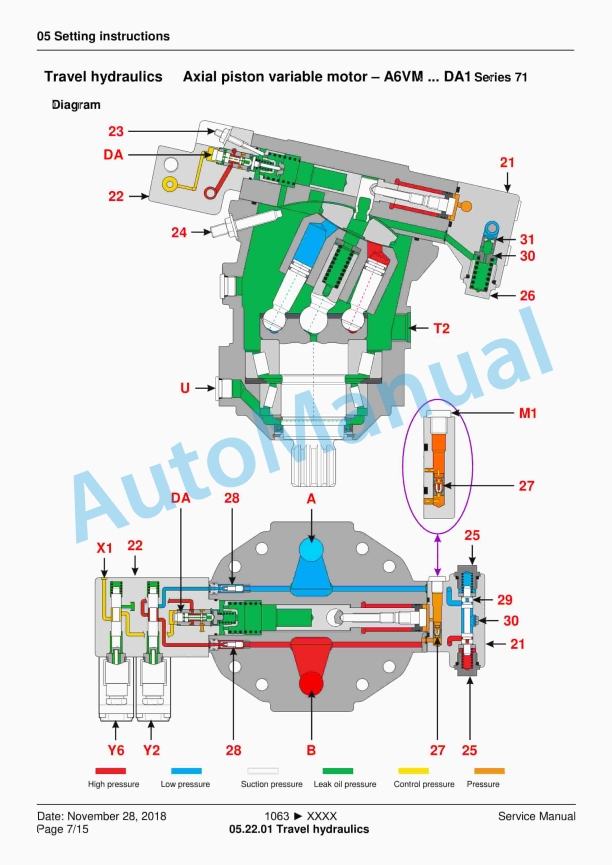
- 1.6.3. Travel hydraulics setting instructions
- 1.6.4. Valve description HDM19WL
- 1.6.5. Service- and parking brake
- 1.7. Functional Description
- 1.7.1. Saug – Rücklauffilter
- 1.7.2. Vorsteuergerät 4TH6
- 1.8. Electrics
- 1.8.1. Kabel- und Stecker Farben
- 1.8.2. Verknüpfungen in Elektoschaltplänen lesen
- 1.8.3. Verknüpfungen am Steuermodul und Display
- 1.8.4. Stromlaufplan Blatt 1
- 1.8.5. Stromlaufplan Blatt 2
- 1.8.6. Stromlaufplan Blatt 3
- 1.8.7. Stromlaufplan Blatt 4
- 1.8.8. Stromlaufplan Blatt 5
- 1.8.9. Stromlaufplan Blatt 6
- 1.8.10. Stromlaufplan Blatt 7
- 1.8.11. Sicherungs- und Relaisbelegung
- 1.9. Maintenance
- 1.9.1. Betriebsstoffspezifikation
- 1.9.2. Inspektionsplan
- 1.10. Operation
- 1.10.1. Betätigung proportional – 3. Hydrauliksteuerkreis
- 1.11. Options
- 1.11.1. Steuerblock – Lastschwingungsdämpfung
- 1.12. Repair Instructions
- 1.12.1. Fitting hydraulic screw connections
- 1.12.2. Adhesive kit cab windows
- 1.13. Diagnosis / Tools
- 1.13.1. Special tools – purchased parts
- 1.13.2. Beschreibung der BDE-Software
- 2. Home to List of Contents


,%202GM(F)(L),%203GM(D)(F)(L),%203HM(F)(L)%20Marine%20Diesel%20Engine%20Service%20Manual&url=https://pdfrepairmanual.com/docs/yanmar-1gm10l-2gmfl-3gmdfl-3hmfl-marine-diesel-engine-service-manual/&media=https://pdfrepairmanual.com/wp-content/uploads/2026/01/yanmar-1gm10l-2gmfl-3gmdfl-3hmfl-marine-diesel-engine-service-manual-1.jpg)


There are no reviews yet.